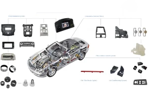
In component manufacturing, dimensional accuracy and breakage risk are often intertwined. The higher the dimensional accuracy requirements, the more complex the part structure (such as thin walls, deep holes, and tiny features). This increases the risk of part breakage caused by stress, Calore, or vibration during machining.
The following provides a systematic breakage prevention solution from the perspectives of materials, processes, equipment, tooling, and testing:
1. Material Level: Compatibility Selection and Pretreatment
(1). Matching Material Properties to Processing Requirements
- Brittle Materials (e.g., Ceramics, Single Crystal Silicon):
Avoid purely hard materials. Toughened ceramics (e.g., ZrO₂-toughened Al₂O₃) can be used to increase fracture toughness by 30%-50%, reducing the risk of chipping. Semiconductor silicon wafers require annealing (600-800°C for 2 hours) before machining to eliminate internal stress and reduce brittle fracture during cutting. - Metal Materials (such as Titanium Alloy and Stainless Steel):
When machining titanium alloy TC4, the annealed state (uniform distribution of α and β phases) is preferred, avoiding the quenched state (hard β phases can easily cause tool chipping). Stainless steel 316L should undergo solution treatment (water cooling at 1050°C) before machining to reduce work hardening and minimize part deformation caused by cutting force fluctuations.
(2). Material Defect Pretreatment
Ultrasonic flaw detection is performed on aluminum alloy 7075 plates to remove internal defects such as pores and slag inclusions to prevent cracking caused by defect propagation during machining (e.g., cracking caused by internal defects when milling thin-walled parts).
2. Process Planning: Staged Machining and Stress Control
(1). “Rough – Semi-finish – Finish” Stepped Machining
- Example: Thin-walled sleeve (0.5mm wall thickness, 50mm diameter)
- Roughing: Leave a 1mm allowance and use a high feed rate (0.5mm/r) for rapid material removal. Control the cutting speed between 100-150m/min to avoid local overheating.
- Semi-finishing: Leave a 0.2mm allowance and cut in two passes, each with a 0.1mm depth of cut. Increase the cutting speed to 200m/min to reduce cutting force accumulation.
- Finishing: Use minimal cutting (0.02mm depth of cut, 0.05mm/r), combined with cold air cooling (-30° C.) to control dimensional deviations and edge chipping caused by thermal deformation.
(2). Stress Relief Process Design
- Deep Hole Machining (1mm diameter, 50mm depth):
Pause every 10mm of machining depth and perform ultrasonic vibration stress relief (20kHz frequency, 5μm amplitude) to prevent cracking in the hole wall due to residual stress concentration. - Thin Sheet Parts (0.1mm thickness):
Use a “layered milling + annealing” cycle: After each 0.02mm of milling thickness, perform a stress relief anneal at 150°C (hold for 1 hour) before continuing machining to minimize warping and cracking of the thin sheet.
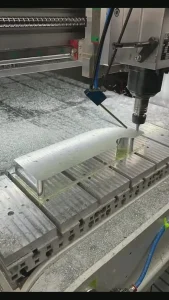
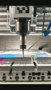
3. Tooling and Fixtures: Reducing Deformation and Vibration
(1). Flexible Clamping Technology
- Vacuum Suction Clamping:
Used for thin sheet parts (such as semiconductor silicon wafers), vacuum pressure (0.08MPa) uniformly holds the workpiece, avoiding deformation and cracking caused by the localized clamping force of traditional fixtures. Flatness error can be controlled within 5μm. - Magnetorheological Fixtures:
Utilize magnetorheological fluid (which solidifies instantaneously under an applied magnetic field) to wrap parts, enabling contactless clamping. Suitable for parts with complex curved surfaces (such as optical lenses), clamping stress is less than 1MPa, preventing edge cracking associated with traditional clamping.
(2). Vibration-Reducing Tooling Design
- Thin-Wall Box Machining:
Filling the workpiece cavity with a polymer damping material (such as polyurethane) increases the natural frequency from 200Hz to 500Hz, avoiding the resonant frequency range of milling (typically 300-400Hz) and reducing vibration-induced cracking of thin walls. - Slender Shaft Turning:
Utilize a steady rest + steady rest combination support system, with support points set every 100mm. Radial runout is controlled within 2μm to prevent shaft fractures caused by chatter during turning.
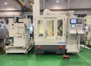
4. Equipment and Environmental Control: Ensuring Precision and Stability
(1). Machine Tool Precision Upgrade
- Spindle Dynamic Balancing:
High-speed spindles (over 30,000 rpm) are dynamically balanced to a residual unbalance of < 1g/mm. This prevents vibration during high-speed rotation that can cause tool chipping and part damage. - Feed Axis Preload:
The linear motor drive shaft applies a 10%-15% preload force to eliminate backlash (<0.5μm) and prevent tool impact damage caused by sudden feed changes during corner machining.
(2). Environmental Stability Control
- Constant Temperature and Humidity Workshop:
Temperature fluctuations are controlled within ±0.5°C, and humidity is maintained at 45%±5%. This prevents aluminum alloy parts from expanding and contracting due to temperature and humidity fluctuations (e.g., for a 100mm long part, every 1°C temperature change results in a dimensional change of approximately 25μm). This can lead to dimensional deviations during finishing and forced cutting. - Vibration Isolation Foundation:
The machine tool is mounted on an air spring vibration isolation device to isolate it from external vibrations (amplitude < 1μm). This is particularly suitable for high-precision applications such as laser processing and electron beam processing, preventing microstructured parts from breaking due to tiny vibrations (e.g., a 0.1mm thick metal mesh).
5. Inspection and Process Monitoring: Real-Time Damage Prevention
(1). Online Inspection and Feedback
- In-Process Dimension Monitoring:
A non-contact laser probe (accuracy ±1μm) measures part dimensions in real time. If a diameter variation exceeds 5μm, processing is automatically paused and cutting parameters are corrected to prevent continued processing that could cause dimensional deviations and potentially fracture the part. - Acoustic Emission (AE) Monitoring:
An AE sensor is installed on the tool. When an abnormal high-frequency signal (>500kHz) is detected during cutting, it is identified as tool chipping or microcracks in the part, prompting immediate shutdown to prevent further damage.
(2). Predicting Breakage Risk
- Finite Element Analysis (FEA):
Before machining, perform cutting simulations on the part to predict stress concentration areas (e.g., thin-wall fillets where stress exceeds 80% of the material’s yield strength are prone to breakage). This allows for pre-emptive process parameter adjustments (e.g., increasing the fillet radius from 0.5mm to 1mm reduces stress by 30%).