The accuracy and quality of CNC machining directly determine the assembly performance and reliability of the workpiece. After machining, systematic inspections are required to ensure that the workpiece meets design requirements. The following are key accuracy and quality inspection requirements, covering core dimensions such as dimensional accuracy, form and position tolerances, and surface quality:
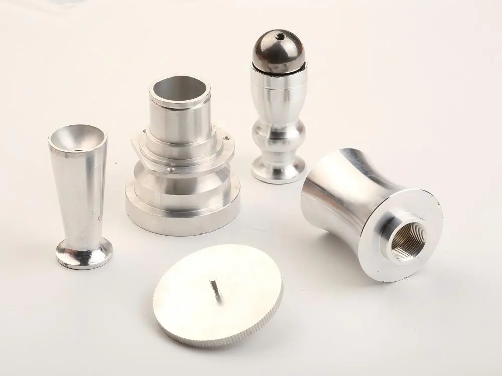
1. Dimensional Accuracy Inspection: Ensuring that Critical Dimensions Meet Design Tolerances
Dimensional accuracy is the most fundamental quality indicator for a workpiece. Both critical dimensions and general dimensions marked on the drawing must be inspected item by item:
Linear Dimensions
Inspection Targets: Length, width, height, hole diameter, groove depth, step thickness, ecc. (e.g., shaft diameter φ20 ± 0.01mm, hole depth 30 + 0.02/-0mm).
Inspection Tools:
General Dimensions (tolerance ≥ ±0.05mm): Vernier caliper (accuracy 0.02mm), micrometer (accuracy 0.001mm);
Precision Dimensions (tolerance < ±0.05mm): Digital micrometer, height gauge (with a marble platform), and 2D imager. Requirements: Measured values must be within the tolerance range indicated on the drawing. Exceeding tolerances (e.g., upper or lower limits exceeding the design values) are not permitted. Particular attention should be paid to mating dimensions (e.g., clearance/interference between the shaft and the hole).
Angular Dimensions
Test Targets: Bevel angles, angles between two planes (e.g., 45° ± 0.1°, 90° ± 0.05°).
Testing Tools: Universal angle ruler (accuracy 2′), angle block gauge (used with a dial indicator), coordinate measuring machine (high-precision angle).
Requirements: Angular deviations must be controlled within the tolerance range to avoid assembly interference (e.g., excessive clearance on bevels) caused by angular deviations.
Thread Dimensions
Test Targets: Thread diameter (major diameter, pitch diameter), thread pitch, and thread angle (e.g., M10×1.5-6H internal threads).
Testing Tools: Thread plug gauges/ring gauges (for testing with a go/no-go gauge, a pass is considered acceptable if the go gauge passes but the no-go gauge does not), thread micrometer (for measuring the pitch diameter). Requirements: Threads must be complete, free of broken or misaligned threads, fit smoothly, and have no binding. Deviations in the mean diameter must meet the specified tolerance grade (e.g., 6H, 6G).
2. Form and Position Tolerance Inspection: Controlling Geometric and Positional Errors
Form and positional tolerances (form and position tolerances) affect the assembly accuracy and motion stability of workpieces. The following items should be inspected specifically:
Form Tolerance
Straightness: Checks the linear deviation of flat or cylindrical surfaces (e.g., guideway straightness ≤ 0.02mm/1000mm). Use a straightedge with a dial indicator or a laser interferometer.
Flatness: Checks the flatness of surfaces (e.g., mold cavity flatness ≤ 0.01mm/500mm). Use a marble platform with a dial indicator or a flatness tester.
Roundness/Cylindricity: Checks the cross-sectional roundness (e.g., shaft roundness ≤ 0.005mm) and overall cylindricity of cylindrical surfaces. Use a roundness tester or a three-dimensional coordinate measuring machine. Requirements: Form errors must not exceed the tolerance value indicated on the drawing (e.g., “○0.01” indicates a roundness tolerance of 0.01mm).
Position Tolerance
Parallelism: The deviation between two planes or axes in parallel (e.g., parallelism of the upper and lower planes of a cover plate ≤ 0.03mm). This is checked using a dial indicator on a marble platform.
Perpendicularity: The deviation between two planes or axes in perpendicularity (e.g., perpendicularity between a hole and an end face ≤ 0.02mm/100mm). This is measured using a square with a dial indicator or a three-dimensional coordinate measuring machine.
Coaxiality: The alignment of the axes of multiple cylindrical segments (e.g., coaxiality of a stepped shaft ≤ 0.01mm). This is measured using a V-block with a dial indicator or a three-dimensional coordinate measuring machine.
Position: The deviation of features such as holes and slots relative to a datum (e.g., array hole position ≤ ±0.05mm). This is checked using a coordinate measuring machine or a gauge (e.g., a locating pin).
Requirement: Position errors must be within the tolerance band. Particular attention must be paid to the selection of the datum (consistent with the datums A, B, and C indicated on the drawing). Iii. Surface Quality Inspection: Ensure Surface Roughness and Integrity
Surface quality affects the workpiece’s wear resistance, sealing, and appearance. Inspection items include:
Surface Roughness (Ra/Rz)
Inspection Target: Microscopic irregularities on machined surfaces (e.g., Ra 1.6μm, Ra 3.2μm). Rough-machined surfaces (e.g., Ra 12.5μm) and fine-machined surfaces (e.g., Ra 0.8μm) must be inspected separately.
Inspection Tool: Roughness meter (contact or optical) is used to measure directly on the workpiece surface and record the Ra value (arithmetic mean deviation).
Requirement: The measured Ra value must be ≤ the value indicated on the drawing (e.g., “Ra 3.2” indicates a value of ≤ 3.2μm). Sealing and friction surfaces must be strictly controlled to avoid leakage or excessive wear.
Surface Defects
Common Defects: Scratches, dents, dents, pores, cracks, burrs, rust, ecc. Inspection Methods:
Visual inspection (under natural light or white light, at a distance of 30-50cm);
Magnifying glass or microscope (to inspect for fine scratches, e.g., scratches >0.1mm on precision parts);
Pentnetrant testing (to inspect for surface cracks, e.g., on high-strength steel parts).
Requirements: Critical surfaces (e.g., bearing seats and sealing surfaces) must not have any defects; defects on non-critical surfaces must be within acceptable limits (e.g., scratch depth ≤ 0.05mm, length ≤ 5mm).
3. Other Key Inspection Items
Burrs and Sharp Edges
All machined edges must be deburred (especially at through-holes, notches, and steps), and sharp edges must be chamfered (e.g., chamfer 0.5mm) to prevent scratches on hands or other parts during assembly.
Inspection Methods: Visual inspection + feel (touch the edge with gloves; no stinging sensation).
Material and Hardness (if required)
Verify that the workpiece material matches the drawing (e.g., 45# acciaio, aluminum alloy 6061). If necessary, use a spectrometer to analyze the composition. If the drawing requires heat treatment (such as quenching or nitriding), a hardness tester must be used to test the surface hardness (e.g., HRC 45-50) to ensure compliance with performance requirements.
Batch Consistency (During Mass Production)
After passing the first-piece inspection, subsequent workpieces must be randomly sampled (e.g., 1 in every 10) to review key dimensions and geometric tolerances to ensure machining stability (deviation fluctuation ≤ 1/3 of the tolerance).
4. Inspection Records and Judgment Criteria
Record Requirements: All inspection data must be recorded in the “CNC Machining Inspection Report,” including actual dimensional values, tolerance ranges, inspection tools, and inspection personnel. Critical dimensions must be accompanied by inspection diagrams (e.g., three-dimensional coordinate measurement reports). Acceptance criteria:
All dimensions, geometric tolerances, and surface quality meet the drawing requirements (no out-of-tolerance items);
Minor defects (such as small scratches on non-critical surfaces) that do not affect performance may be accepted with customer approval;
Defects that exceed tolerances or affect assembly/performance (such as cracks or thread gauges that pass) are considered unacceptable and require rework or scrapping.

