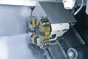
En CNC 4 ejes mecanizado, Mejorar la eficiencia y garantizar la calidad requiere un esfuerzo coordinado en múltiples aspectos, incluida la planificación de procesos, programming optimization, equipment debugging, and tool management, while also balancing machining stability and precision control. The following are specific methods:
CNC 4-axis Machining
1. Process Planning: Improving Efficiency and Quality from the Start
Optimize Process Integration and Reduce Setups
- Leverage the 4-axis’s “multi-surface machining in one setup” capability to integrate multiple processes (molienda, perforación, biselado, and tapping) into the same program.
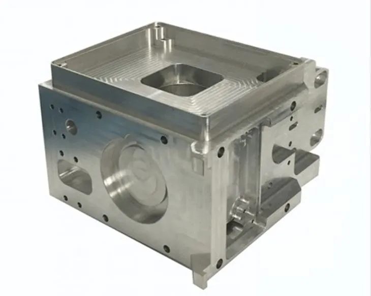
- Ejemplo: when machining a box part with an inclined hole, the A-axis can be rotated to sequentially machine the front, side, and inclined surfaces, avoiding the positioning errors caused by multiple setups in 3-axis machining.
- (Reducing the number of setups by one increases efficiency by 20%-30%, and achieves better dimensional consistency.)
Reference Surfaces and Locating Holes
- Prioritize machining of reference surfaces and locating holes, using them as a reference for subsequent machining.
- Ensures positional accuracy of each feature (such as the perpendicularity of the inclined hole to the plane) (error ≤ 0.01mm).
- Rationally divide the roughing and finishing stages.
Roughing
- High feed rates and large depths of cut (3-5mm, 1000-2000mm/min feed).
- Use high-speed steel or coated carbide tools (P.EJ., TiAlN-coated end mills).
- Use A-axis rotation to adjust the workpiece angle to avoid tool-workpiece interference.
Refinamiento
- Smaller depth of cut (0.1-0.3mm), alta velocidad (8000-15000rpm).
- Use high-precision tools (ball end mills, boring tools).
- Enable the machine’s “high-precision mode” (P.EJ., “Contour Adaptive Control” on Siemens systems).
- Ensure contour accuracy (error ≤ 0.005mm) and surface roughness (Ra ≤ 1.6μm).
2. Programming and Toolpath Optimization: Reducing Backlash and Interference
Efficient 4-Axis Toolpath Design
- Use spiral or circular toolpaths instead of reciprocating toolpaths.
- For curved surfaces (P.EJ., impeller blades), spiral toolpaths reduce tool lift times (by 30%) and provide stable cutting forces, preventing surface marks.
Optimize Rotary Axis (A/B) Motion
- Avoid frequent direction changes (P.EJ., A-axis rapidly switching from +30° to -30°).
- Use “smooth transition” in CAM software (P.EJ., UG) to gradually change rotation angle, reducing vibration.
- For high-precision workpieces, surface roughness Ra reduced by 0.4-0.8μm.
Safe Height and Feed Method
- Roughing: safe height 5-10mm.
- Refinamiento: safe height 2-3mm.
- Use circular or oblique feeds to avoid tool impact from vertical cuts (extend tool life by 20%).
Interference Check and Simulation Verification
- After programming, use CAM 3D simulation to check interference between tool, toolholder, fixture, and workpiece.
- Ejemplo: turbine disks—ensure toolholder does not collide with hub at extreme A-axis angles.
- For batch production: test cut 1–2 parts, measure critical dimensions, then fine-tune parameters.
3. Equipment and Tooling: Ensuring Stability and Accuracy
Machine Tool Parameter Calibration and Optimization
- Regularly calibrate rotary axis positioning accuracy and repeatability.
- Use laser interferometer: positioning error ≤ 0.005mm/360°, repeatability ≤ 0.002mm.
- Adjust servo parameters based on material (shorter acceleration for aluminum, longer for steel).
- Enable “feedforward control” to reduce following error.
Thermal Error Compensation
- For long machining times (>8 hours), enable thermal error compensation.
- Reduces errors in long shafts by 50%.
Fixture Design and Workpiece Clamping
- Fixtures must be lightweight and rigid (dentro 60% of rotary axis load).
- Use ribs to increase rigidity (≤ 0.001mm/100N).
- Shafts: 3-jaw chuck + center combo (coaxiality ≤ 0.003mm).
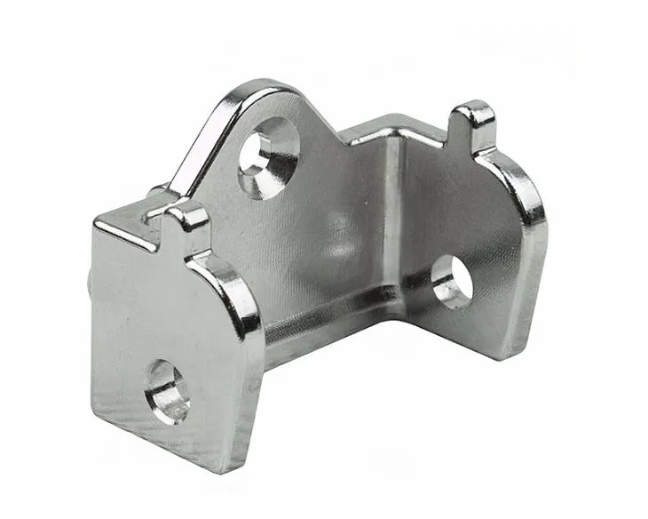
- Special-shaped parts: custom tooling (P.EJ., blade fixture “one-face, two-pin” positioning ≤ 0.005mm).
- Avoid over-positioning and excessive clamping force (prevents deformation).
4. Tool Selection and Cutting Parameters: Balancing Efficiency and Life
Tool Matching
- Roughing: trowel milling cutter or face milling cutter (multi-edge, 10-16mm dia. for <100mm workpieces).
- Refinamiento: ball-end milling cutter (R angle = min curvature radius) or bullnose cutter (reduces tip wear).
- Bevel hole machining: high-speed steel or solid carbide drill with guide edge.
- Deep holes (>3×D): use peck drilling.
Cutting Parameters (45 steel example)
- Rough milling: VC = 100-150 m/min, fz = 0.1-0.2 mm/tooth, ap = 3-5 mm.
- Fine milling: VC = 150-200 m/min, fz = 0.05-0.1 mm/tooth, ap = 0.1-0.3 mm.
- Aluminio: increase to VC = 300-500 m/min.
- Titanium alloys: reduce to VC = 30-50 m/min.
Coolant
- Use high-pressure coolant (10-20 bar).
- Especially for stainless steel and titanium alloys.
- Reduces tool temp (extends life by 30%) and flushes chips.
5. Quality Inspection and Process Monitoring: Promptly Identify Problems
Online Inspection and Compensation
- Workpiece probe (P.EJ., Renishaw OMP40-2) checks dimensions after roughing, before finishing.
- Automatic correction of tool length or rotary axis angle (accuracy up to 0.001mm).
- For curved parts: laser profiler measures contour accuracy, adjusts toolpath dynamically.
Tool Condition Monitoring
- Sonar or vibration sensor monitors tool vibration (100-500Hz normal).
- Abnormal frequency → alarm + auto shutdown.
- producción por lotes: check tool wear every 50–100 parts.
- Replace if flank wear > 0.3mm.
6. Efficiency Improvement Techniques for Mass Production
Program Preview and Breakpoint Resume
- CNC “Program Preview” (P.EJ., FANUC AI Advanced Preview) analyzes 100–200 toolpath segments in advance.
- Makes motion smoother, increases feed speed 10%-15%.
- Breakpoint saving: resume from stop point, avoiding repeat machining (saves 20%-50%).
Automation Integration
- Robotic loading/unloading: reduces handling time (30–60s → 10–15s).
- Quick-change fixture system (P.EJ., EROWA): changeover time reduced (30 min → 5 min).
- Suitable for high-mix, small-batch production.