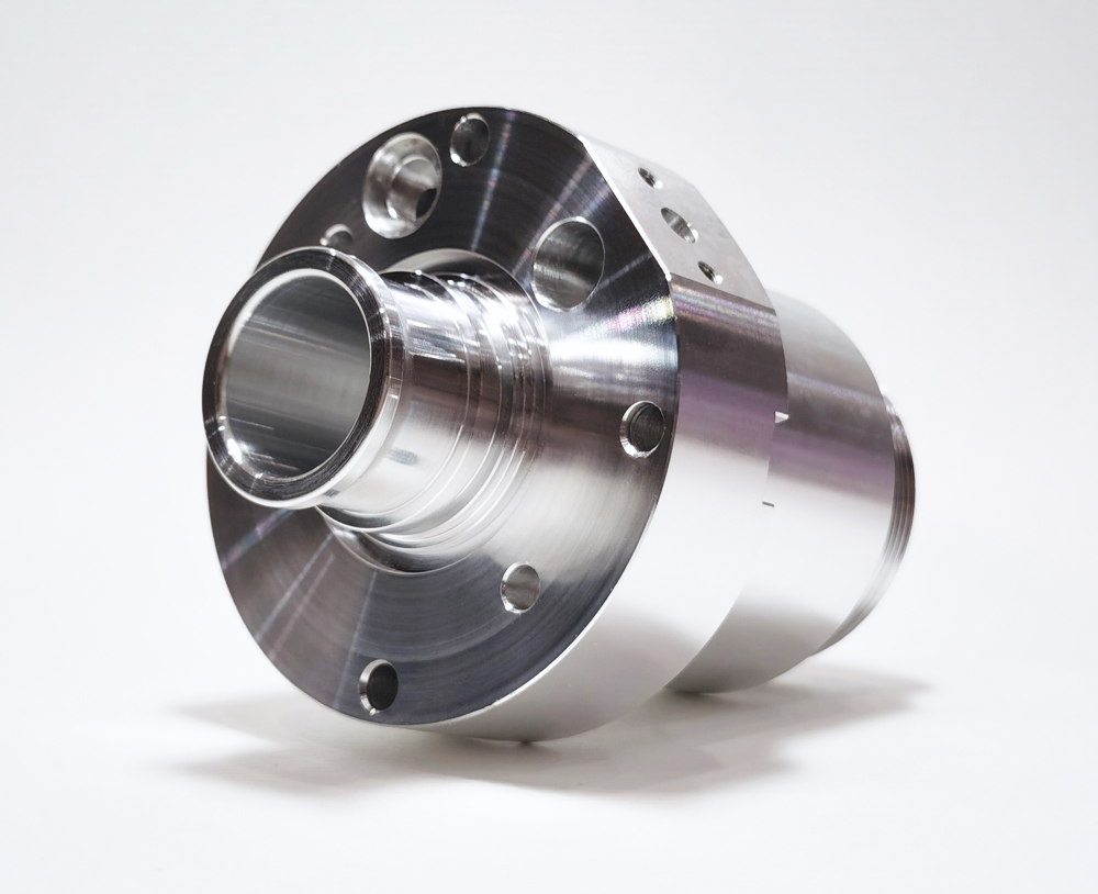
非標準のハードウェア部品の処理品質 (非標準仕様と特定のニーズに合わせてカスタマイズされた金属部品) directly impacts equipment assembly accuracy and service life. Due to their complex shapes and diverse precision requirements (such as dimensional tolerances, surface finish, and mechanical properties), comprehensive control is required from the design source, process planning, machining process, and testing and verification. The following are key measures to ensure quality when processing non-standard hardware parts:
Design Phase: Define Quality Standards to Avoid Process Risks
- Establish Clear Technical Requirements
Quantify Key Parameters: Clearly mark all quality indicators on the drawings to avoid vague descriptions:
Dimensional tolerances: 例えば, “φ10±0.01mm” (not “approximately 10mm”), and determine the accuracy grade based on the application scenario (例えば, IT6-IT8 for mating parts, IT10-IT12 for non-mating parts). Surface quality: surface roughness (例えば, Ra1.6μm), coating requirements (例えば, zinc coating thickness 8-12μm, no rust after 48 hours of salt spray testing), and whether deburring is required (sharp corner radius R0.1-0.5mm).
Mechanical properties: If strength requirements are involved, specify the material heat treatment method (例えば, 45 steel tempered to HB220-250) and hardness range (例えば, 304 stainless steel hardness ≤ HV200).
Process feasibility review:
Review drawings with the fabrication manufacturer to avoid design features that exceed machining capabilities (例えば, when deep hole machining requires an aspect ratio greater than 10, conventional drilling machines cannot maintain straightness, requiring the use of deep-hole drills).
Optimize structural details: 例えば, change “inner right angles” に “R0.5mm radius” (to facilitate tool feed and avoid machining residue), and design “thin walls (<1mm)” as reinforcing ribs (to prevent machining deformation). - Material Selection and Quality Control
Matching Materials and Processes: Select materials based on the processing method (例えば, choose 40Cr over 20 steel for heat-treated parts; choose alloy tool steel Cr12 for precision-ground parts) to avoid processing defects caused by material properties (例えば, stainless steel tends to stick to knives, so choose 316 stainless steel containing molybdenum to improve cutting performance).
Raw Material Inspection:
Require suppliers to provide material quality assurance certificates (including composition and mechanical property reports). Conduct sampling inspections when necessary (例えば, using a spectrometer to analyze chemical composition to ensure that no impurities exceed standards).
Inspect the raw material condition: 例えば, check for bends in round steel (straightness >0.5mm/m will affect processing accuracy) and for cracks in sheet metal (especially cold-rolled sheet, which requires surface inspection for scratches).
プロセス計画: Selecting the Right Solution to Reduce Quality Fluctuations
- Developing a Reasonable Processing Process
Sort by Precision Gradient: Follow the sequence of “rough machining → semi-finishing → finishing” to avoid part deformation due to excessive cutting forces.
例えば, when machining a shaft part with a step, the process should be “rough turning (leaving a 2-3mm allowance) → quenching and heat treatment → semi-finishing (leaving a 0.5-1mm allowance) → grinding (to final dimensions)” rather than directly machining the part in one go.
Prioritize Critical Processes: Schedule features requiring high precision (such as locating holes and mating surfaces) to subsequent processes to minimize the impact of cumulative errors from previous processes. (例えば, for a box part, first machine the datum surface, then use that datum surface to locate and machine the rest of the hole system.) - Select Appropriate Processing Equipment and Cutting Tools
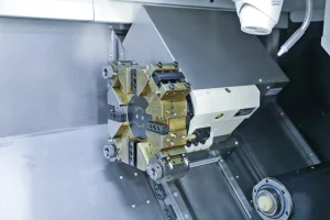
Equipment Accuracy Matching:
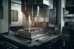
High-precision parts (tolerance ≤ 0.01mm) require precision machining equipment (such as CNC grinders and machining centers, with positioning accuracy ≤ 0.005mm);
Ordinary-precision parts (tolerance 0.1-0.5mm) can be produced using conventional lathes and milling machines, but regular equipment calibration is required (例えば, monthly inspection of lathe spindle runout ≤ 0.01mm).
Tool Selection:
Select tool material based on the material (例えば, carbide tools for machining aluminum alloys, ceramic tools for machining titanium alloys).
Tool Parameter Optimization: 例えば, when milling stainless steel, use a larger rake angle (10°-15°) to reduce cutting forces and minimize surface roughness.
iii. Processing Process: Real-Time Monitoring to Prevent Defects - First-Part Inspection: Verify Process Validation
Before mass production, process one to three first-part pieces and inspect key indicators item by item:
Measure dimensions with calipers and micrometers, check flatness and perpendicularity with a dial indicator, and inspect surface quality with a roughness tester.
After the first part passes inspection, record processing parameters (切断速度など, 送り速度, and tool type) as a benchmark for mass production. - Process Parameter Control
Maintain stable cutting conditions:
Avoid arbitrary adjustments to processing parameters (such as spindle speed and feed rate). Cutting parameters must remain within the range specified in the process documentation (例えば, when turning 45 鋼鉄, スピード 800-1200 rpm, 餌 0.1-0.2 mm/min).
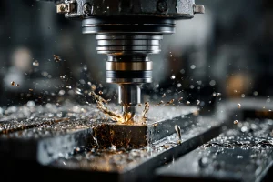
Monitor cutting fluid conditions: Ensure adequate cooling and lubrication (例えば, cutting fluid concentration 5%-8% during grinding to prevent workpiece burns). Change the cutting fluid regularly to prevent impurities from scratching the surface.
Reduce clamping deformation:
Adopt appropriate clamping methods: 例えば, use soft jaws (copper jaws) or specialized fixtures when machining thin-walled parts (to avoid pinching and deformation), and support long-axis parts with a toolholder and steady rest (to prevent bending).
Control clamping force:
Use a torque wrench to set the clamping force (例えば, for aluminum alloy parts, the clamping force should be ≤ 500N to avoid crushing). - Self-inspection and mutual inspection between processes
After completing each process, the operator must self-inspect key dimensions (例えば, hole diameter and depth after drilling) and record them on an inspection sheet.
The operator of the next process must inspect the quality of the previous process (if burrs are found in the previous process, they should be returned for processing) to prevent defect transfer.
Inspection and Verification: Comprehensively Confirm Quality Compliance
- Final Inspection Covers All Items
Dimensional Accuracy:
Use general measuring tools (キャリパー, micrometers) to check standard dimensions, and precision measuring tools (such as a coordinate measuring machine) to check complex geometric tolerances (such as position and coaxiality).
For critical mating dimensions (such as bearing holes), verify with go/no-go gauges (例えば, a φ20H7 hole will pass with a φ20H7 go gauge, but not with a no-go gauge).
Surface Quality:
Visually inspect for scratches, へこみ, and cracks (using a 5x-10x magnifying glass).
Use a coating thickness gauge to check coating thickness, and use a salt spray tester to verify corrosion resistance (testing for the required time as specified in the drawing).
Mechanical Properties:
For heat-treated parts, use a hardness tester (例えば, Rockwell hardness tester for HRC, Brinell hardness tester for HB).
Critical load-bearing parts (such as shafts and gears) undergo tensile testing (testing tensile strength and yield strength). - Special Testing (for High-Demand Parts)
Nondestructive Testing: For parts subject to high pressure or impact (such as hydraulic valve blocks), ultrasonic testing is used to detect internal cracks, and magnetic particle testing is used to detect surface defects.
Assembly Simulation Testing: Test-fit parts with mating components to check for problems such as binding and excessive clearance (例えば, gears and shafts must rotate freely without play).
v. Quality Traceability and Continuous Improvement - Establishing Complete Quality Records
Record the processing date, operator, equipment number, and test data for each batch of parts to create a traceable quality file. This facilitates troubleshooting when problems arise (例えば, if a batch of parts has dimensional deviations, the machine calibration can be traced back to that day). - Defect Analysis and Process Optimization
Collect common quality issues (such as dimensional deviations, surface roughness, and deformation) and analyze their root causes.
If dimensional instability is caused by tool wear, the tool replacement cycle should be shortened.
If material deformation is caused by heat treatment, the heat treatment process should be adjusted (例えば, adding stress relief annealing).