結論を先に
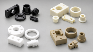
CNC machining tolerance depends on material, 機能タイプ, 部品の形状, 固定具, 熱を切る, 機械の状態, 工具の摩耗, and inspection method. For general CNC machined metal parts, common standard tolerances are often around ±0.05–0.13 mm, depending on supplier, drawing requirements, and feature complexity. For plastics, tolerances are often looser because thermal expansion, moisture absorption, and clamping deformation can affect final dimensions.
Tighter tolerances such as ±0.01mm または ±0.005mm are possible, but they should not be treated as default tolerances for every CNC part. They are usually realistic only for selected critical features when the design, material, fixture, toolpath, 機械の状態, and inspection method all support the requirement.
This CNC machining tolerance chart is a practical engineering reference. It does not replace drawing review or DFM analysis, but it helps designers, buyers, and engineers understand what tolerance levels are realistic for different materials, プロセス, and feature types.
What This CNC Machining Tolerance Chart Means
A tolerance chart should not be read as a universal guarantee. A number such as ±0.005mm may be achievable on a short precision bore, a bearing seat, or a controlled mating feature, but it may be unrealistic across a long thin-wall part, a large flat surface, or a soft plastic component.
In real CNC machining, tolerance capability is affected by:
- Material stability and internal residual stress
- Part size and overall dimensions
- Wall thickness and structural rigidity
- Cutting heat and coolant application
- Tool deflection and spindle runout
- Fixture design and clamping pressure
- Measurement and inspection methods
- Workshop temperature and part stabilization
This is why a good tolerance strategy does not apply tight tolerances everywhere. It applies them only where function requires them.
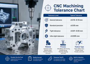
Quick CNC Machining Tolerance Chart
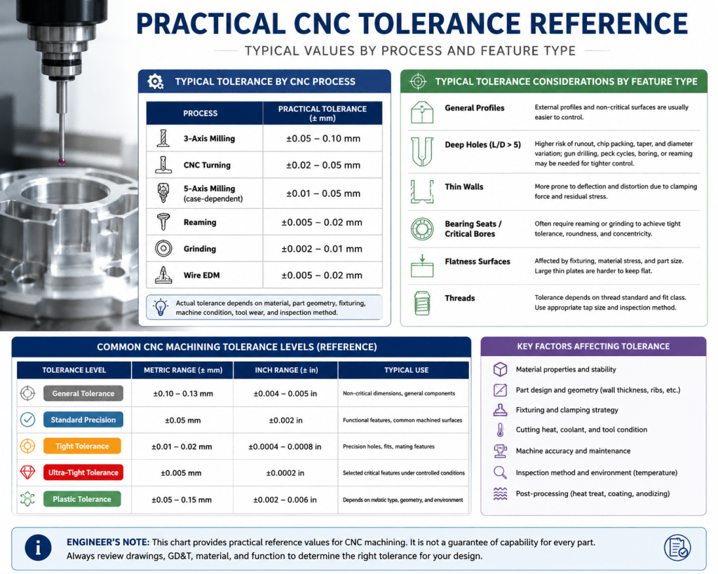
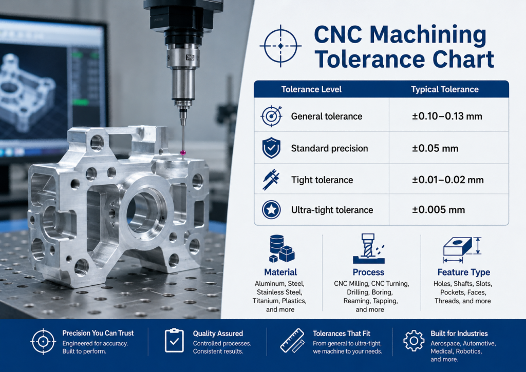
The table below gives a practical starting point for CNC tolerance planning. It combines common industry expectations with real machining risk factors.
| Tolerance Level | Metric Range | Inch Range | Typical Use |
|---|---|---|---|
| 一般公差 | ±0.10–0.13 mm | ±0.004–0.005 in | Non-critical CNC metal parts |
| Standard precision | ±0.05 mm | ±0.002 in | Functional features and common machined surfaces |
| Tight tolerance | ±0.01–0.02 mm | ±0.0004–0.0008 in | Bearing seats, precision holes, mating features |
| Ultra-tight tolerance | ±0.005mm | ±0.0002 in | Selected critical features only |
| Plastic CNC tolerance | ±0.05–0.15 mm | ±0.002–0.006 in | Depends strongly on plastic type and geometry |
Many online manufacturing platforms treat ±0.005 in as a common local CNC tolerance for metals, while plastics often require wider tolerance windows. Some precision CNC services can quote tighter values, but these typically depend on 2D drawing review, GD&T requirements, inspection methods, and engineering approval.
ISO 2768 General Tolerance Reference
ISO 2768 is commonly used for general tolerances when individual dimensions do not have specific tolerance callouts. It is useful for drawing simplification, but it should not be confused with guaranteed CNC shop capability.
| Nominal Length Range | ISO 2768 Fine | ISO 2768 Medium |
|---|---|---|
| 0.5–3 mm | ±0.05 mm | ±0.10 mm |
| 3–6 mm | ±0.05 mm | ±0.10 mm |
| 6–30 mm | ±0.10 mm | ±0.20 mm |
| 30–120 mm | ±0.15 mm | ±0.30 mm |
| 120–400 mm | ±0.20 mm | ±0.50 mm |
| 400–1000 mm | ±0.30 mm | ±0.80 mm |
| 1000–2000 mm | ±0.50 mm | ±1.20 mm |
ISO 2768 is a general tolerance reference for dimensions without individual tolerance indications. If a critical feature needs tighter control, it should be clearly specified on the drawing with appropriate tolerance, フィット, or GD&T callouts.
Practical Tolerance Reference by Material
Different materials behave differently during machining. A stable aluminum part and a soft PTFE part should not be treated with the same tolerance expectation, even if they are produced on the same CNC machining center.
| 材料 | Practical CNC Tolerance Range | Tight Tolerance Risk | Engineering Note |
|---|---|---|---|
| 6061 アルミニウム | ±0.05–0.10 mm | 低い | Stable, 機械加工が簡単, good default choice |
| 7075 アルミニウム | ±0.05–0.10 mm | Medium | Stronger than 6061 but higher cutting stress |
| 5052 アルミニウム | ±0.05–0.10 mm | Medium | 良好な腐食抵抗, lower strength |
| ステンレス鋼 | ±0.05–0.10 mm | Medium | Work hardening and heat can affect accuracy |
| Tool Steel / Hardened Steel | ±0.05–0.10 mm | Medium to high | Tool wear and heat control matter |
| チタン | ±0.05–0.15 mm | 高い | Poor heat dissipation and tool wear risk |
| インコネル | ±0.05–0.15 mm | 高い | Work hardening and heat resistance increase cost |
| POM / デルリン | ±0.05–0.10 mm | Medium | Stable among plastics, good for precision parts |
| ピーク | ±0.02–0.10 mm | Medium | Stable but expensive; process control matters |
| PTFE | ±0.10 mm or looser | 高い | Soft and easily deformed under clamping |
| ナイロン | ±0.10 mm or looser | 高い | Moisture absorption can change final dimensions |
These values should be used as a practical engineering reference, not as absolute standards. Real tolerance depends on drawing requirements, 機能タイプ, パーツサイズ, material batch, 治具の設計, post-processing, and inspection method.
Coating Note for Aluminum Components
For aluminum parts that require Type III hard anodizing, tolerance planning must account for coating thickness and dimensional change after finishing. Hard anodized layers can reach around 25–50 μm depending on specification and process, and only part of that thickness grows outward from the original surface.
Bearing seats, sliding fits, ねじ付きフィーチャー, sealing surfaces, and press-fit areas may require machining offset, masking, post-finishing reaming, or a clear coating allowance on the drawing.
This is especially important for 6061 そして 7075 aluminum components where the final functional fit is measured after anodizing, not before finishing.
Tolerance by Feature Type
A tolerance callout should be evaluated by feature type. Some features are naturally easier to control, while others are sensitive to tool deflection, 切りくずの排出, clamping, or stress release.
| Feature Type | Typical Difficulty | なぜそれが重要なのか |
|---|---|---|
| External profile | Easier | Good tool access and easy inspection |
| Simple holes | Medium | Drill runout and tool wear affect size |
| Reamed holes | Easier to control | Reaming improves diameter consistency |
| Deep holes | Harder | Deep holes with L/D > 5 increase runout, chip packing, taper, and diameter variation risk. Gun drilling, peck cycles, つまらない, or reaming may be needed for tighter control. |
| Thin walls | Harder | Clamping and residual stress cause movement |
| Bearing seats | Harder | Roundness, concentricity, and fit matter |
| Flatness surfaces | Harder | Fixturing and material stress affect flatness |
| Threaded holes | Medium | Thread depth and fit class matter |
| Long shafts | Harder | Deflection and thermal growth affect accuracy |
| Large plates | Harder | Flatness can change after material removal |
For tight assemblies, feature tolerance should also be checked together with CNC machining tolerance stack-up. A single dimension may look acceptable, but several small deviations can accumulate and cause assembly failure.
Tolerance by CNC Process
Different CNC operations create different tolerance risks. ミリング, 旋回, つまらない, リーミング, and grinding should not be treated as identical processes.
| CNC Process | Practical Tolerance Expectation | メモ |
|---|---|---|
| CNCフライス加工 | ±0.05–0.10 mm | Good for general prismatic parts |
| CNC旋削加工 | ±0.02–0.05 mm | Good for round parts and shafts |
| Precision boring | ±0.01–0.02 mm | Useful for bearing seats and accurate holes |
| Reaming | ±0.005–0.02 mm | Good for controlled hole diameter |
| Grinding | ±0.002–0.01 mm | Used for very tight surfaces and hardened parts |
| Wire EDM | ±0.005–0.02 mm | Good for hard materials and precise profiles |
| 5-軸加工 | Case-dependent | Reduces setups but still depends on fixture and inspection |
The process does not guarantee the tolerance by itself. 例えば, 5-axis machining can reduce setup error and improve access to complex features, but thin walls, long tool reach, unstable clamping, and poor datum strategy can still create dimensional problems.
When ±0.005 mm Is Realistic
あ ±0.005 mm tolerance is not a normal default tolerance for every CNC part. It is realistic only for selected critical features when the design, material, fixture, toolpath, 機械の状態, and inspection method all support that requirement.
実際に, ±0.005 mm is more realistic for:
- Short precision holes
- Reamed or precision bored features
- Bearing seats
- Precise alignment dowel holes
- Controlled mating faces with rigid structures
- Small, symmetrical high-value functional features
- Parts measured under stable temperature conditions
Temperature Control Factor
For ultra-tight tolerances such as ±0.005mm, temperature control becomes critical. Aluminum expands by about 23 μm per meter for every 1°C temperature rise, so even small temperature differences between machining and inspection can affect the final measurement.
Critical dimensions should be finished and verified under stable temperature conditions, commonly around 20℃ when high-precision inspection is required.
It is much harder to hold ±0.005 mm across:
- Long parts
- Thin-wall components
- Soft plastics
- Deep pockets
- Stress-sensitive geometries
- Large flatness surfaces
- Features with poor datum definition
For critical dimensions, the drawing should clearly identify the functional features that truly need tight control. This allows the machining process and inspection plan to focus on the right areas.
Why Tight Tolerance Becomes Expensive
Tight tolerance is not just a number on a drawing. It changes the entire manufacturing process.
A tighter tolerance may require:
- Slower cutting speeds
- Additional semi-finishing passes
- Custom precision fixtures
- Dedicated clamping jigs
- Post-machining stress relief
- Thermal stabilization periods
- Constant tool wear monitoring
- More frequent tool replacement
- CMM inspection reports
- More scrap risk
- Longer lead time
例えば, changing a general dimension from ±0.10 mm に ±0.01mm may require more stable fixturing, better tool control, and additional inspection. Changing it again to ±0.005mm may require full process validation and controlled measurement conditions.
This is why over-tolerancing can increase cost without improving the part’s function.
Hidden Cost of Over-Tolerancing
Over-tolerancing is one of the most common ways to increase CNC machining cost. A drawing that applies ±0.01mm to every feature may look precise, but most parts only need tight tolerance on functional areas.
Tight tolerances increase:
- Machining time
- Inspection cost
- Fixture complexity
- ツールウェア
- Scrap risk
- Supplier review time
- Quotation uncertainty
A better strategy is to apply tight tolerance only to critical features such as:
- Bearing seats
- Sealing surfaces
- Alignment holes
- Press-fit features
- Mating interfaces
- Datum-related surfaces
- Features that affect assembly function
For non-critical external profiles, cosmetic surfaces, or clearance features, looser tolerances are often more cost-effective.
For thin-wall or deformation-sensitive parts, レビュー how to reduce deformation during CNC machining before locking the final tolerance requirements on your drawing.
Material Movement and Deformation Risk
Many tolerance problems are not caused by machine inaccuracy alone. They are caused by material movement.
Common causes include:
- Internal stress release after roughing
- Uneven material removal
- Over-clamping
- Thin-wall vibration
- Thermal expansion
- Tool pressure
- Poor datum selection
- Measuring the part too soon after machining
This is why thin-wall parts, プラスチック, チタン, ステンレス鋼, and Inconel often require more careful process planning than simple aluminum blocks.
Machine condition and tool wear also affect final accuracy. For a broader explanation, see our guide on CNC machining accuracy factors.
Inspection Method Matters
A tolerance is only meaningful if it can be measured reliably.
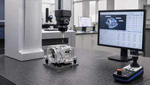
For simple features, calipers or micrometers may be enough. For complex geometry, tight GD&T, true position, 平坦度, roundness, or concentricity, a CMM is often required.
| Inspection Method | 最適な用途 | Limitation |
|---|---|---|
| Caliper | General external dimensions | Not ideal for tight tolerance |
| Micrometer | Shafts, thickness, small precision features | Limited geometry access |
| Bore gauge | Hole diameter and roundness checks | Requires setup and master reference |
| Height gauge | Step heights and simple datums | Less suitable for complex 3D geometry |
| 三次元測定機検査 | GD&T, true position, 平坦度, 複雑な部品 | Higher inspection setup time |
| Optical measurement | Small features and non-contact inspection | Depends on surface reflectivity and lighting |
For critical CNC parts, buyers should ask how the supplier verifies the dimension, not just whether the machine can cut it. Professional CMM inspection for CNC machined parts is especially important for high-precision aerospace, 自動車, 医学, and automation components.
Plastic CNC Tolerance Considerations
Plastic CNC parts often need a different tolerance strategy from metals. Many plastics have higher thermal expansion, lower stiffness, or moisture sensitivity.
例えば:
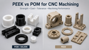
- POM / デルリン is relatively stable and suitable for many precision plastic components.
- ピーク offers better dimensional stability and heat resistance but is expensive.
- PTFE is soft and can deform under clamping pressure.
- ナイロン can absorb moisture, which may shift dimensions after machining.
For a broader comparison, see our guide on best plastics for CNC machining. If you are choosing between high-performance plastics, 私たちの PEEK vs POM for CNC machining guide explains the difference between a general precision plastic and a premium engineering plastic.
エンジニアのメモ
In our shop, tolerance review starts before machining. We do not treat every dimension equally. 初め, we identify which features control fit, 封印, alignment, rotation, or assembly. Then we evaluate whether the material, geometry, fixture, and inspection method can support the requested tolerance.
例えば, a ±0.005 mm bearing seat may be realistic if the feature is short, rigid, properly fixtured, and inspected after thermal stabilization. But the same tolerance across a long thin-wall aluminum housing or a PTFE part may be impractical or unnecessary.
Good tolerance control is not about promising the smallest number. It is about applying the right tolerance to the right feature.
Practical Tolerance Selection Guide
Use this simple logic when setting CNC tolerances:
- Use ±0.10 mm for non-critical general dimensions.
- Use ±0.05 mm for common functional CNC metal features.
- Use ±0.01–0.02 mm for precision holes, fits, and mating features.
- Use ±0.005mm only for selected critical features after DFM review.
- Use looser tolerance for plastics unless the material and geometry support tight control.
- Avoid applying tight tolerance to every dimension.
- Define critical datums clearly before adding GD&T.
- Match tolerance requirements with inspection method.
If a tolerance affects assembly, 封印, rotation, sliding, or bearing fit, it deserves tighter control. If it does not affect function, over-tightening it may only increase cost.
よくある質問: CNC加工公差表
What is the standard tolerance for CNC machining?
For many CNC machined metal parts, common standard tolerance is around ±0.05–0.13 mm, depending on supplier, material, 機能タイプ, geometry, and drawing requirements.
Can CNC machining hold ±0.005 mm?
はい, CNC machining can hold ±0.005mm on selected critical features, but it requires controlled machining, stable fixturing, suitable material, tool condition control, and temperature-stabilized inspection. It should not be applied blindly to every feature.
Is ±0.01 mm possible in CNC machining?
はい, ±0.01mm is possible for certain CNC features, especially short precision holes, bearing seats, and controlled mating surfaces. 長さ, thin, soft, or stress-sensitive parts are more difficult.
What tolerance should I use for aluminum CNC parts?
For many aluminum CNC parts, ±0.05 mm is a practical starting point for functional features. Tighter tolerances may be possible depending on geometry, clamping, toolpath, and post-processing coating requirements.
What tolerance should I use for plastic CNC parts?
Plastic CNC parts often require looser tolerances than metal parts because of thermal expansion, moisture absorption, and clamping deformation. POM and PEEK are generally more stable than PTFE or Nylon.
Why does tight tolerance increase CNC machining cost?
Tight tolerance increases machining time, tool control requirements, fixture complexity, inspection cost, and scrap risk. It should be applied only to functional features that truly require it.
Is ISO 2768 the same as CNC machining capability?
いいえ. ISO 2768 is a general tolerance reference for drawings without individual tolerance callouts. It does not automatically define what every CNC shop can guarantee for every material and feature.
結論
A CNC machining tolerance chart is useful only when it is used with engineering judgment. General CNC metal parts may use tolerances around ±0.05–0.13 mm, while precision features may require ±0.01–0.02 mm. Ultra-tight tolerances such as ±0.005mm are possible, but only for selected critical features under controlled conditions.
The right tolerance depends on material, 機能タイプ, geometry, 固定具, 熱を切る, tool condition, post-processing, and inspection method. Instead of applying tight tolerances everywhere, the better approach is to identify which features truly affect function and apply precision where it matters.
迅速かつ効率的, we help customers review drawings, identify tolerance risks, and choose practical machining and inspection strategies before production. Send us your 2D drawing or 3D model, and our engineers can help evaluate whether your tolerance requirements are realistic, 費用対効果の高い, and production-ready.