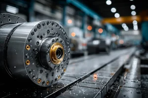
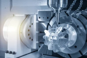
Photochemical machining, also known as photoetching, is highly efficient for producing parts with complex geometries or numerous holes. Processing these parts using processes such as embossing, punching, laser cutting, or wire EDM can result in burrs and mechanical or thermal distortion.
Chemical machining for parts processing involves outputting tool files specifically designed for etching with compensation factors to a high-resolution photoplotter, producing matching front-to-back images. For workpieces with complex geometries, such as irregular shapes or numerous holes, photochemical machining is often more economical than embossing, punching, laser cutting, or wire EDM.
Photoetching is suitable for a wide range of metalworking processes, including embossing, die-cutting, punching, laser and water jet cutting, and wire EDM. Its particular advantages include:
- The ability to process very thin materials, down to 0.0005 inches (≈12.7 μm).
- The ability to produce complex geometries, including fine meshes, grids, and grilles.
- The ability to achieve dimensional tolerances typically within ±10% of the metal thickness for very thin materials.
- The ability to quickly and cost-effectively produce both small and large batches.
- No thermal stress or mechanical deformation in the metal.
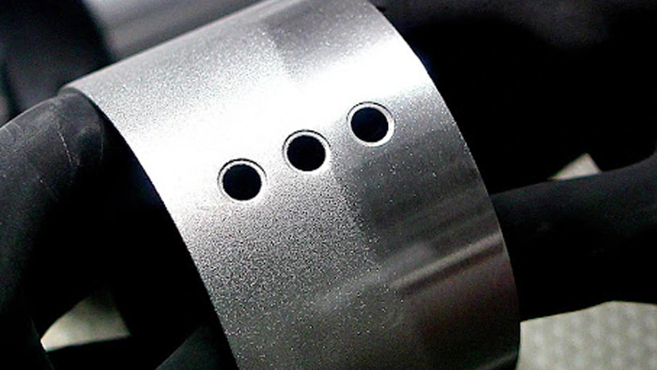
The chemical machining process for part production utilizes inexpensive, rapidly formed tooling that can accommodate a series of part configurations or multiple iterations of a single configuration, accelerating the development process. Photoetched parts can be produced in as little as 2–3 days from sheet metal thicknesses ranging 0.001 to 0.050 inches (≈25 μm to 1.27 mm). Part sizes range from as small as 0.100 inches (≈2.54 mm) with 0.004-inch (≈0.10 mm) features to as large as 24 x 60 inches (≈610 x 1524 mm).
Tolerances and Feature Size
Photoetching typically produces features with positional tolerances within the nominal 0.001-inch (≈25 μm) drawing specification. Etching dimensional tolerances depend on material thickness and sheet size. As a general rule, larger tolerances correlate with larger plate sizes and lower part costs.
Typical Tolerances:
- ±10% of material thickness for thicknesses <0.010 inches (≈0.25 mm).
- For thicknesses 0.010–0.020 inches (≈0.25–0.51 mm): ±0.0015 to ±0.0025 inches (≈38–64 μm).
- For thicknesses 0.021–0.035 inches (≈0.53–0.89 mm): ±0.005 inches (≈127 μm).
- For thicknesses >0.035 inches (>0.89 mm): approximately ±20% of the material thickness.
Hole and Slot Dimensions
- Small holes or micro-slots must be at least 110% of the material thickness for materials up to 0.020 inches (≈0.51 mm) thick.
- For metals thicker than 0.020 inches, the requirement is 120% of the material thickness.
- The thin area between holes or slots must be at least equal to the material thickness.
- The minor dimension of the inner and outer radii must equal the material thickness.

