We know that the emergence of CNC equipment is a significant milestone in technological advancement. It effectively addresses complex, precise, and high-volume and low-volume part machining challenges. It is a flexible, highly efficient automated system.
When programmers utilize CNC equipment for machining, they first need to conduct a process analysis and select the appropriate equipment based on the material, profile, and machining accuracy of the part being machined. They then customize the machining plan, determining the machining sequence, the tools, fixtures, and cutting parameters for each step, and more. Today, we’ll examine these key points in turn:
1. Equipment Selection
When selecting parts for machining, two scenarios typically arise.
- First, with the part drawing and the blank, you need to select the appropriate CNC equipment for processing.
- Second, once you have CNC equipment, you need to choose the right machine to process the part.
In either case, key factors to consider include the part’s material and type, the complexity of the contour, size, machining accuracy, the need for heat treatment, and the number of parts.
In summary, there are three key points:
- The technical requirements for machining the part must be met to produce the desired product.
- It must be conducive to increasing machining capacity.
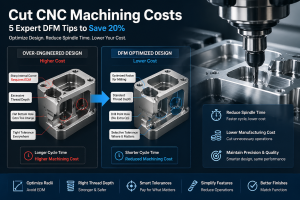
- Processing costs must be minimized.
2. CNC Machining Parts Processing
CNC machining processes are very broad. Here, we will only analyze them from the perspectives of machining possibilities and convenience.
First, the dimensional data provided on the part drawing should conform to the code.
Principle of Programming Convenience
- The dimensioning method on part drawings should be suitable for the processing characteristics of CNC equipment.
On part drawings, unified base dimensions or direct coordinate dimensions should be used. This method not only facilitates programming and the coordination of dimension lines, but also greatly facilitates maintaining consistency between the design base, process base, and inspection base, as well as the programming origin.
Because part designers typically consider assembly and other operational characteristics when dimensioning, they are forced to use a localized, decentralized dimensioning method. This can cause significant inconvenience during process scheduling and CNC machining. CNC machining typically requires high precision and repeatable positioning accuracy, preventing large cumulative errors that could compromise operational characteristics. Therefore, it is recommended to replace localized, decentralized dimensioning with dimensioning based on a unified base or direct coordinate dimensions.
- The geometric elements that make up the part’s outline must be sufficient.
When programming manually, the coordinates of the base points or nodes must be calculated. When programming automatically, all geometric elements that make up the part’s outline must be defined.
Therefore, when analyzing the part drawing, it’s important to determine whether the given conditions for the geometric elements are sufficient. For example, an arc and a line, or another arc, may be tangent to each other, but the dimensions given in the drawing may result in them intersecting or disjointing when calculating the tangents. This inadequate condition of the geometric elements can hinder programming. When encountering this situation, consult with the part designer to resolve it.
Structural Processability
Secondly, the structural processability of each machined part should conform to the characteristics of CNC machining.
- It’s best to use relatively uniform geometric dimensions for the part’s internal cavity and external shape. This reduces tool specifications and the need for tool changes, making programming easier and significantly improving production efficiency.
- The size of the internal groove fillet determines the tool diameter, so the radius should not be too large. The quality of the part’s processability is related to the height of the machined contour and the size of the transition arc radius.
- When milling the bottom surface of the part, the radius R of the groove bottom fillet should not be too large.
- A unified datum should be used for positioning. During CNC machining, if a unified positioning datum is not used, the contour position and dimensions of the two surfaces will be inconsistent after reassembly. To avoid these problems and ensure accurate positioning between two clamping operations, a unified positioning datum should be used.
It’s best to have suitable empty spaces on the part for datum holes. If not, process holes should be set as datum holes. If it’s not possible to create a process hole, at least a finely machined surface should be used as a unified reference to reduce errors caused by two clampings. Furthermore, the required machining accuracy and dimensional tolerances should be determined, and any excess dimensions that might cause conflicts or block dimensions that could affect process scheduling should be analyzed.
About RapidEfficient
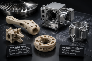
RapidEfficient specializes in high-precision CNC machining with 18 years of experience. Its products cover medical, communications, optics, drones, intelligent robots, automotive, and office automation parts.
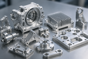
The company’s CNC machining centers include four-axis, five-axis, and linkage machine tools and are equipped with precision projectors, three-coordinate measuring machines, spectrometers, and other precision testing equipment.
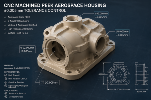
- Machining accuracy: up to 0.01mm
- Testing accuracy: up to 0.001mm