1. Introduction
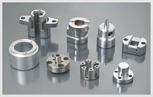
In the ever-evolving landscape of modern manufacturing, the production of complex parts has emerged as a cornerstone. These intricate components, integral to a myriad of industries ranging from aerospace and automotive to medical and electronics, demand the utmost precision and efficiency in their fabrication. The advent of Computer Numerical Control (CNC) machining has been a game-changer, revolutionizing the way complex parts are manufactured. Among the arsenal of tools available to CNC machinists, MasterCAM stands out as a powerful software solution that has redefined the possibilities in this domain.
Complex parts, by their very nature, pose significant challenges. Their intricate geometries, tight tolerances, and often unique material requirements necessitate advanced machining techniques. Traditional machining methods often fall short in meeting these demands, leading to increased production times, higher costs, and potential inaccuracies. This is where CNC machining steps in, offering a level of precision and repeatability that was previously unimaginable.
MasterCAM, developed by CNC Software, Inc., has become an industry standard for a reason. It seamlessly integrates Computer-Aided Design (CAD) and Computer-Aided Manufacturing (CAM) capabilities, providing machinists with a comprehensive suite of tools to design, simulate, and generate the necessary code for CNC machines. With its user-friendly interface and extensive feature set, MasterCAM empowers manufacturers to take on the most complex of projects with confidence.
In this article, we will delve deep into the world of CNC machining of complex parts using MasterCAM. We will explore its various features, understand how it optimizes the machining process, and examine real-world case studies that highlight its effectiveness. Whether you are a seasoned machinist looking to enhance your skills or a manufacturing professional seeking to understand the latest trends in complex part production, this article promises to provide valuable insights. So, let’s embark on this journey to unlock the potential of MasterCAM in the realm of complex part CNC machining.
2. Understanding Complex Parts
2.1 Characteristics
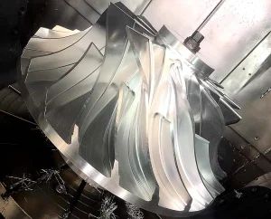
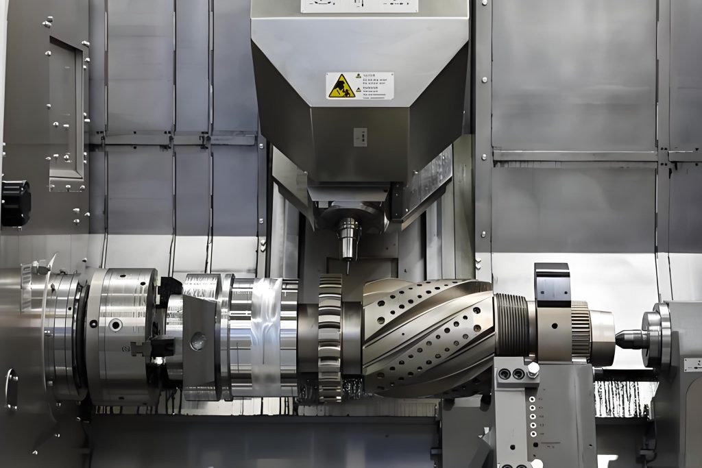
Complex parts possess a unique set of characteristics that set them apart from their simpler counterparts. Geometrically, they often feature intricate shapes with multiple curves, surfaces, and undercuts. These complex geometries can be found in components like turbine blades, where aerodynamic efficiency demands precise and elaborate contours. In the medical field, implants such as hip replacements require custom shapes to fit individual anatomies perfectly, adding another layer of complexity.
Tight tolerances are the norm for complex parts. In aerospace applications, for instance, a minuscule deviation in the dimensions of a critical component could lead to catastrophic consequences. Tolerances as tight as a few microns are not uncommon, necessitating machining processes that can achieve and maintain such precision. This level of accuracy is far beyond what traditional machining methods can reliably deliver.
Material selection for complex parts also plays a crucial role. High-strength alloys, exotic metals, and advanced composites are frequently used to meet specific performance requirements. These materials, while offering superior properties, present their own set of challenges. Some superalloys used in jet engines, for example, are extremely difficult to machine due to their hardness and heat resistance. Machining them requires specialized tools and techniques to avoid excessive tool wear and ensure the integrity of the finished part.
2.2 Challenges in Machining
The machining of complex parts is fraught with difficulties. Traditional machining methods struggle to handle the intricate geometries, often resulting in longer production times and higher costs. Manual programming for multi-axis machining, for instance, is a laborious and error-prone process. It requires highly skilled machinists with extensive experience, and even then, the risk of errors remains significant.
Tool path generation is another major hurdle. Determining the optimal path for the cutting tool to follow is a complex task, especially when dealing with complex shapes. Inefficient tool paths can lead to excessive tool wear, longer machining times, and poor surface finishes. In some cases, the wrong tool path can even cause damage to the part or the machine itself.
Dealing with material deformation is a constant concern. During machining, the removal of material generates heat and stress, which can cause the part to warp or distort. This is particularly problematic for thin-walled or delicate components. In the automotive industry, for example, the machining of aluminum alloy engine parts with thin walls requires careful consideration of cutting parameters to minimize deformation and ensure dimensional accuracy.
Quality control is equally challenging. Verifying that a complex part meets the required tolerances and surface finish standards demands advanced inspection techniques. Traditional measurement tools may not be sufficient, and the use of coordinate measuring machines (CMMs) and other high-precision inspection equipment becomes essential. However, these tools can be expensive and require specialized operators, adding to the overall cost and complexity of the machining process.
3. MasterCAM: A Powerful Tool
3.1 Overview
MasterCAM has been a leading player in the CAD/CAM software arena for decades. Its comprehensive suite of features caters to a wide range of machining requirements, making it a go-to choice for manufacturers worldwide.
At its core, MasterCAM offers robust 2D and 3D design capabilities. Users can create intricate part geometries from scratch or import existing CAD files from other popular software. The intuitive design interface allows for quick and accurate model creation, whether it’s a simple 2D profile or a complex 3D surface. This flexibility in design is crucial as it forms the foundation for the subsequent machining operations.
One of the standout features of MasterCAM is its advanced toolpath generation. It employs sophisticated algorithms to calculate the most efficient paths for cutting tools, taking into account factors such as tool geometry, material properties, and machining parameters. This not only reduces machining time but also minimizes tool wear and maximizes the quality of the finished part. The software supports a vast array of machining strategies, including milling, turning, drilling, and wire EDM, among others, making it suitable for a diverse range of CNC machines.
Simulation is another key aspect of MasterCAM. Before any actual machining takes place, users can simulate the entire process within the software environment. This virtual machining allows them to visualize how the part will be cut, check for potential collisions between the tool, workpiece, and fixtures, and make necessary adjustments to the toolpath or setup. This preemptive approach significantly reduces the risk of errors and costly mistakes on the shop floor.
Post-processing in MasterCAM is equally impressive. It comes with a vast library of post-processors tailored to different CNC controllers. These post-processors convert the generated toolpath data into machine-readable code, ensuring seamless communication between the software and the actual machining equipment. This means that whether you’re using a FANUC, Siemens, or Haas machine, MasterCAM can generate the appropriate code to drive it.
3.2 Advantages in Complex Part Machining
When it comes to machining complex parts, MasterCAM truly shines. Its visual programming interface simplifies the otherwise complex task of creating toolpaths for intricate geometries. Machinists can interactively define the cutting parameters, select the appropriate tools, and watch as the software generates the optimized paths in real-time. This visual feedback not only speeds up the programming process but also gives the user a better understanding of how the machining will unfold.
The software’s ability to handle multi-axis machining is a game-changer for complex part production. With support for up to 5-axis simultaneous motion, MasterCAM can tackle parts with complex angles, undercuts, and freeform surfaces. This level of control allows for the creation of highly precise and intricate features that would be nearly impossible to achieve with traditional 3-axis machining. For example, in the aerospace industry, turbine blades with complex aerodynamic profiles can be machined to exacting tolerances using MasterCAM’s multi-axis capabilities.
MasterCAM’s simulation capabilities are especially critical for complex parts. Given the high cost and tight tolerances associated with these components, any errors or collisions during machining can be disastrous. The software’s detailed simulation not only detects potential collisions but also provides insights into the surface finish, material removal rates, and machining forces. This information enables machinists to fine-tune the process parameters to achieve the desired results.
Another advantage is the automatic code generation. Once the toolpath and machining parameters are set, MasterCAM can quickly generate the NC code required for the CNC machine. This eliminates the need for manual coding, which is not only time-consuming but also prone to errors. The generated code is optimized for the specific machine and controller, ensuring smooth and efficient operation on the shop floor. Overall, MasterCAM’s combination of design, programming, simulation, and post-processing capabilities makes it an indispensable tool for machining complex parts with speed, precision, and reliability.
4. The Machining Process
4.1 Part Modeling
The first step in CNC machining using MasterCAM is creating an accurate and detailed model of the complex part. This can be achieved in several ways. If you already have a 2D or 3D design in a format like DWG or STEP, you can import it directly into MasterCAM. The software supports a wide range of file formats, ensuring compatibility with most design software used in the industry.
Once imported, you may need to make some adjustments or refinements to the model. This could involve cleaning up the geometry, repairing any gaps or overlaps, and ensuring that all the features are properly defined. For example, if you’re machining a mold with intricate cavities, any inaccuracies in the model could lead to problems during the actual machining.
In cases where you don’t have an existing model, MasterCAM provides powerful design tools to create one from scratch. You can use the 2D drafting tools to sketch out the basic profiles of the part. These sketches can then be extruded, revolved, or swept to form 3D solids. The software’s parametric design capabilities allow you to easily modify the dimensions and shapes of the features, making it convenient to iterate and optimize the design.
During the modeling process, it’s crucial to pay attention to the details. The tolerances you set at this stage will directly impact the final machining accuracy. You also need to consider the manufacturability of the design. Some features that look great on paper may be difficult or even impossible to machine. MasterCAM’s analysis tools can help you identify potential issues early on, such as thin walls that could deform during machining or sharp corners that might cause tool breakage.
4.2 Toolpath Planning
With the part model in place, the next critical step is planning the toolpaths. This is where MasterCAM truly showcases its power. The software offers a vast array of machining strategies, each tailored to specific types of features and materials.
For milling operations, you can choose from strategies like pocket milling, contour milling, and surface milling. Pocket milling is ideal for creating recessed areas or cavities, while contour milling is used to machine the outer edges and profiles of the part. Surface milling, on the other hand, is designed for machining complex 3D surfaces with high precision. When selecting a milling strategy, you need to consider factors such as the shape of the feature, the required surface finish, and the cutting tool’s capabilities.
Tool selection is equally important. Different materials require different types of cutting tools. For machining aluminum, for instance, you might use high-speed steel or carbide end mills. However, when dealing with hardened steel or exotic alloys, you may need to opt for more specialized tools like ceramic or diamond-coated cutters. MasterCAM provides a comprehensive tool library that allows you to select the appropriate tool based on the material and machining requirements. You can also customize the tool parameters, such as the diameter, length, and number of flutes.
Once the tool and machining strategy are chosen, you need to set the cutting parameters. This includes the spindle speed, feed rate, and cutting depth. These parameters need to be carefully optimized to balance the machining efficiency and the tool life. Too high a spindle speed or feed rate can lead to excessive tool wear and poor surface finish, while too low a cutting depth can increase the machining time. MasterCAM’s built-in machining databases and optimization algorithms can provide initial recommendations, but you may need to fine-tune these based on your actual machining experience and the specific characteristics of your machine.
During toolpath planning, it’s also essential to consider the machine’s capabilities and limitations. If you’re using a 3-axis machine, you need to plan the toolpaths in a way that avoids collisions and ensures that all the features can be machined. For more complex parts, a multi-axis machine may be required. MasterCAM’s support for up to 5-axis machining allows you to create toolpaths that can reach otherwise inaccessible areas and achieve complex geometries with ease.
4.3 Simulation and Verification
Before sending the generated toolpaths to the CNC machine, it’s imperative to conduct a thorough simulation and verification. This step can save you significant time, money, and potential headaches on the shop floor.
MasterCAM’s simulation capabilities are remarkably detailed. You can virtually watch the entire machining process unfold, with the cutting tool moving through the material exactly as it would on the actual machine. The simulation takes into account factors such as the tool’s geometry, the material removal rate, and the machine’s kinematics. This allows you to detect potential collisions between the tool, workpiece, and fixtures well in advance.
During the simulation, you can also check the surface finish of the machined part. If the toolpaths are not optimized, you may notice uneven surfaces or visible tool marks. By making adjustments to the toolpaths or cutting parameters, you can improve the surface quality to meet the required standards. Additionally, the simulation can provide insights into the machining forces. Excessive forces can cause vibrations, leading to inaccuracies and potential damage to the machine. If you notice high forces in the simulation, you can modify the toolpaths or reduce the cutting parameters to mitigate this issue.
Verification goes beyond just the simulation. You can use MasterCAM’s measurement tools to check the dimensions of the machined part in the virtual environment. This ensures that the part will meet the specified tolerances once it’s actually machined. If any discrepancies are found, you can go back and make the necessary adjustments to the toolpaths or the model itself. Overall, the simulation and verification process in MasterCAM is a critical safeguard that significantly increases the chances of a successful machining operation.
4.4 NC Code Generation and Machining
Once you’re satisfied with the simulation and verification results, it’s time to generate the NC code. MasterCAM’s post-processing capabilities come into play here. The software has a vast library of post-processors, each designed to work with specific CNC controllers. Whether you’re using a FANUC, Siemens, Haas, or any other popular controller, chances are MasterCAM has a suitable post-processor.
The post-processor takes the toolpath data generated by MasterCAM and converts it into machine-readable NC code. This code contains all the instructions the CNC machine needs to execute the machining operation, including the tool movements, spindle speeds, and feed rates. During the post-processing stage, you can also customize certain aspects of the code, such as the program number, block skip functions, and tool compensation settings.
After generating the NC code, it’s transferred to the CNC machine. This can be done via a direct connection, such as a USB or Ethernet cable, or through a networked file transfer protocol. Once the machine receives the code, it’s ready to start machining. However, the process doesn’t end there. It’s crucial to monitor the machining operation closely. Keep an eye on the cutting process, listen for any unusual sounds that could indicate tool breakage or machine problems, and check the chips being produced to ensure they’re of the right size and shape.
During machining, you may need to make some adjustments based on the actual conditions. If you notice excessive tool wear, you might need to reduce the feed rate or change the tool. If the surface finish isn’t meeting the requirements, you can make minor tweaks to the spindle speed or cutting depth. By carefully monitoring and adjusting the machining process, you can ensure that the final complex part meets all the desired specifications.
5. Rapidefficient in CNC Machining Market
5.1 What is Rapidefficient
Rapidefficient, in the context of CNC machining, represents a paradigm shift towards achieving faster and more efficient production processes. It embodies a holistic approach that integrates advanced machining techniques, optimized workflows, and state-of-the-art technologies. At its core, Rapidefficient focuses on streamlining every aspect of the CNC machining journey, from initial part design to the final finished product.
This concept emphasizes the use of high-speed machining strategies that capitalize on the capabilities of modern CNC machines. By carefully selecting cutting tools, optimizing toolpaths, and precisely controlling machining parameters, Rapidefficient aims to reduce cycle times significantly. For instance, in the production of complex aluminum alloy parts, rapid spindle speeds and aggressive feed rates can be employed, provided that the tooling and machine can handle the stress. This not only accelerates the material removal process but also minimizes the overall production time.
Moreover, Rapidefficient is about optimizing the entire manufacturing flow. It involves intelligent job scheduling, where multiple parts or projects are sequenced in the most efficient order to minimize machine idle time and setup changes. Additionally, it incorporates real-time monitoring and feedback systems that allow operators to make immediate adjustments to the machining process. If a tool is showing signs of excessive wear during a complex milling operation, the system can alert the operator to change it promptly, preventing costly scrap parts and further downtime.
Quality assurance is an integral part of Rapidefficient as well. While speed is crucial, it cannot come at the expense of the finished product’s integrity. Advanced inspection techniques and in-process quality control measures are implemented to ensure that each complex part meets the strictest tolerances and surface finish requirements. This combination of speed, efficiency, and quality makes Rapidefficient a highly sought-after approach in today’s competitive CNC machining market.
5.2 Its Value and Significance
The value of Rapidefficient in the CNC machining market cannot be overstated. Firstly, it directly translates to shorter production lead times. In industries such as automotive and electronics, where time-to-market is a critical factor, being able to manufacture complex parts rapidly can give companies a significant competitive edge. For example, a car manufacturer that can quickly produce custom engine components using Rapidefficient techniques can launch new models faster, capturing market share ahead of competitors.
Secondly, Rapidefficient boosts overall productivity. By optimizing toolpaths and machining parameters, more parts can be produced in the same amount of time. This increased output capacity not only meets growing market demands but also allows manufacturers to take on more orders, thereby enhancing their revenue streams. In the aerospace sector, where the demand for precision-engineered components is constantly on the rise, higher productivity enabled by Rapidefficient processes is essential to keep up with production schedules.
Another crucial aspect is cost reduction. Faster machining times mean lower labor costs per part, as well as reduced energy consumption. Additionally, minimizing scrap rates through better quality control saves on material costs. For small and medium-sized enterprises (SMEs) operating in the CNC machining space, these cost savings can be the difference between profitability and struggling to stay afloat.
Rapidefficient also caters to the growing trend of customized manufacturing. As customers increasingly demand personalized products, the ability to quickly and efficiently produce complex, one-off parts is invaluable. Whether it’s a bespoke medical implant or a custom-designed electronic enclosure, Rapidefficient techniques enable manufacturers to meet these unique requirements without sacrificing quality or incurring exorbitant costs.
In the broader context, Rapidefficient is driving innovation in the CNC machining industry. It encourages the adoption of new technologies, such as artificial intelligence for process optimization and advanced materials for better tooling. This continuous evolution not only benefits individual manufacturers but also propels the entire manufacturing sector forward, making it more competitive on the global stage.
6. Case Studies
6.1 Aerospace Component Machining
In the aerospace industry, the demand for complex, high-precision components is ever-present. Consider the case of a leading aerospace manufacturer tasked with producing a titanium alloy turbine blade. The blade’s aerodynamic design required intricate 3D surfaces with tight tolerances of just a few microns.
Using MasterCAM, the engineers first imported the CAD model of the blade. The software’s advanced surface analysis tools helped identify potential machining issues, such as areas with steep gradients that could cause tool deflection. With the model refined, they proceeded to plan the toolpaths. MasterCAM’s 5-axis milling capabilities were crucial here. By enabling simultaneous movement of multiple axes, the cutting tool could access all areas of the blade, even those with complex undercuts.
Rapidefficient techniques were employed to optimize the machining process. High-speed machining strategies were implemented, with carefully selected carbide end mills and optimized cutting parameters. The spindle speed was set at a staggering 20,000 RPM, allowing for rapid material removal while maintaining the required surface finish. During the simulation phase in MasterCAM, potential collisions between the tool and the blade were detected and resolved, ensuring a smooth machining process.
The results were remarkable. The production time for each turbine blade was reduced by 30% compared to traditional methods. The surface finish achieved was well within the required Ra 0.8 micrometer standard, eliminating the need for extensive post-machining polishing. Moreover, the dimensional accuracy was spot-on, with less than 0.005 mm deviation from the nominal dimensions, ensuring optimal performance of the blades in the jet engine.
6.2 Medical Implant Fabrication
In the medical field, custom implants are becoming increasingly common. A medical device company needed to produce a patient-specific hip implant made of a biocompatible cobalt-chrome alloy. The implant had a complex geometry, designed to fit the patient’s unique anatomy precisely.
MasterCAM was used to design the implant from scratch. The software’s parametric design features allowed the engineers to quickly make adjustments based on the patient’s medical imaging data. Once the design was finalized, toolpath planning began. Given the hardness of the cobalt-chrome alloy, diamond-coated cutting tools were selected. MasterCAM’s adaptive milling strategy was employed, which dynamically adjusted the toolpath based on the material removal rate, minimizing tool wear and machining time.
Rapidefficient principles were integrated throughout the process. The company utilized a just-in-time production approach, enabled by MasterCAM’s quick programming and setup capabilities. This meant that the implant could be manufactured and delivered to the surgeon in a matter of days, rather than weeks. During machining, real-time monitoring systems were in place to ensure that the implant’s surface finish and tolerances were maintained. Any deviations were immediately corrected, reducing the risk of scrapping the expensive implant.
The outcome was a high-quality hip implant that met all the surgeon’s requirements. The patient experienced a faster recovery time, thanks to the precise fit of the implant. The company also saw a significant reduction in production costs, with a 25% decrease in labor hours and a 15% reduction in material waste compared to previous manufacturing methods.
6.3 Automotive Engine Part Production
The automotive industry is constantly striving to improve engine performance and fuel efficiency, which often requires complex and precisely machined parts. A major automotive manufacturer was developing a new aluminum alloy cylinder head for its next-generation engine. The cylinder head featured intricate cooling channels and valve seats with tight tolerances.
MasterCAM played a pivotal role in the production process. The engineers imported the CAD model of the cylinder head and used MasterCAM’s mold design capabilities to optimize the layout of the cooling channels. Toolpath generation was then carried out, with a focus on minimizing machining time while ensuring the required surface finish. Multi-axis milling was used to machine the complex valve seat geometries accurately.
Rapidefficient strategies were implemented to meet the high-volume production demands. High-speed machining was combined with optimized tooling to reduce cycle times. The company also adopted a lean manufacturing approach, leveraging MasterCAM’s ability to streamline the production flow. By carefully sequencing the machining operations and minimizing setup times, the production rate of cylinder heads increased by 40%.
Quality control was enhanced through MasterCAM’s simulation and verification features. The virtual machining environment allowed the engineers to identify and address potential issues before the actual machining began. This led to a significant reduction in scrap rates, from 5% to less than 1%. The final cylinder heads met all the performance and durability requirements, contributing to the overall success of the new engine model.
7. Tips and Best Practices
7.1 Optimizing Tool Selection
The selection of appropriate tools is paramount in CNC machining, especially when dealing with complex parts. The choice of cutting tools can significantly impact the machining process’s efficiency, accuracy, and overall success. Different materials and part geometries demand specific tool characteristics. For instance, when machining titanium alloys commonly used in aerospace components, carbide or ceramic tools with specialized coatings are often preferred due to their hardness and heat resistance. These coatings can reduce friction, dissipate heat more effectively, and prolong tool life.
Tool geometry also plays a crucial role. The number of flutes on a milling cutter, for example, affects the chip evacuation rate and the cutting forces. A higher flute count can increase the material removal rate but may also require more power. Additionally, the helix angle of the flutes influences the smoothness of the cut and the tool’s ability to handle different materials. For softer materials like aluminum, a higher helix angle can provide a better finish, while for tougher alloys, a more aggressive helix angle might be necessary for efficient cutting.
Regular tool maintenance is equally important. Dull or damaged tools can lead to poor surface finishes, increased machining times, and even part rejection. Machinists should routinely inspect tools for wear, chipping, or breakage. Using tool presetting systems can save valuable setup time and ensure accurate tool positioning. Moreover, proper tool storage to prevent corrosion and damage is a simple yet often overlooked aspect of tool management. By carefully considering these factors and implementing a comprehensive tool management strategy, manufacturers can optimize the machining process and achieve superior results.
7.2 Parameter Settings for Maximum Efficiency
Achieving maximum efficiency in CNC machining hinges on precise parameter settings. Cutting parameters such as spindle speed, feed rate, and cutting depth must be carefully calibrated to balance productivity and tool longevity. These parameters are interdependent and vary depending on factors like material hardness, tool type, and machine capabilities.
Spindle speed is a critical factor. Too low a speed can result in inefficient material removal and poor surface finish, while excessive speed can cause tool overheating and premature wear. For example, when machining aluminum, relatively high spindle speeds can be employed due to the material’s softness, allowing for rapid cutting. In contrast, for hardened steels, lower speeds are necessary to prevent tool damage. Machining handbooks and material data sheets can provide initial guidelines, but fine-tuning based on actual machining trials is often required.
Feed rate determines the speed at which the cutting tool moves through the material. A higher feed rate can reduce machining time but may also increase cutting forces. If the feed rate is too high, it can lead to tool deflection, vibration, and inaccurate cuts. On the other hand, a too-low feed rate wastes time and can cause built-up edge formation. Machinists need to find the optimal feed rate that maximizes material removal while maintaining dimensional accuracy.
Cutting depth affects both the machining efficiency and the tool’s load. Deeper cuts can remove more material in a single pass, but they also subject the tool to greater stress. It’s essential to consider the tool’s geometry, the machine’s power, and the material’s properties when determining the cutting depth. In some cases, multiple passes with shallower cuts might be more suitable to ensure tool integrity and part quality.
Continuous monitoring and adjustment of these parameters during machining are crucial. Real-time feedback from sensors, visual inspection of the cutting process, and analysis of the finished part’s quality can all inform necessary parameter tweaks. By mastering the art of parameter optimization, manufacturers can achieve significant improvements in productivity and cost-effectiveness.
7.3 Quality Control and Inspection
Quality control is the linchpin of successful CNC machining, particularly for complex parts where tight tolerances and high surface finish standards are the norm. Implementing a robust quality control system throughout the machining process is essential to catch defects early and ensure the final product meets or exceeds specifications.
During the machining process, in-process inspection tools like dial indicators, micrometers, and optical comparators can be used to monitor critical dimensions. For example, in the production of a precision-engineered automotive part, frequent measurements of bore diameters, shaft lengths, and surface profiles can help detect any deviations from the nominal dimensions. Any discrepancies can then be corrected promptly by adjusting the toolpath, tool wear compensation, or machining parameters.
Sampling inspection is another common practice. Instead of inspecting every single part, a statistically significant sample is chosen and subjected to detailed measurement and analysis. This approach saves time while still providing a reliable indication of the overall production quality. If the sample reveals a trend of out-of-tolerance parts, corrective actions can be taken on the entire batch, such as recalibrating the machine, replacing worn tools, or revisiting the machining strategy.
Non-destructive testing methods like ultrasonic inspection, magnetic particle inspection, and X-ray tomography can also be employed, especially for parts where internal defects could compromise performance. In the aerospace and medical industries, where component integrity is critical, these advanced inspection techniques are often mandatory. For instance, X-ray tomography can detect hidden voids or cracks inside a complex titanium alloy aerospace component, ensuring its structural soundness.
In the event of quality issues, a comprehensive traceability system is invaluable. By documenting every step of the machining process, from raw material selection to final finishing, manufacturers can quickly identify the root cause of the problem. This includes recording tool changes, machining parameters, operator shifts, and any other relevant information. Armed with this data, corrective and preventive actions can be implemented, minimizing the recurrence of quality problems and enhancing overall production quality.
8. Conclusion
In conclusion, the combination of MasterCAM and Rapidefficient represents a formidable force in the world of CNC machining of complex parts. MasterCAM’s comprehensive suite of design, programming, simulation, and post-processing capabilities empowers manufacturers to overcome the numerous challenges posed by intricate geometries, tight tolerances, and demanding material requirements. Its user-friendly interface and powerful algorithms have made it an indispensable tool across industries such as aerospace, automotive, and medical.
Rapidefficient, on the other hand, injects a new level of speed, productivity, and cost-effectiveness into the machining process. By optimizing every aspect of production, from toolpath selection to real-time monitoring and quality control, it enables manufacturers to meet the ever-increasing demands of modern markets. The ability to rapidly produce high-quality, complex parts not only enhances competitiveness but also paves the way for innovation and customization.
As we look ahead, the future of CNC machining of complex parts holds even more promise. Continued advancements in software technology, machine capabilities, and materials science will further expand the boundaries of what is possible. Manufacturers who embrace these technologies and strive for continuous improvement will be well-positioned to thrive in the dynamic manufacturing landscape. Whether you are a machinist looking to enhance your skills or a business owner seeking to optimize your production processes, exploring the potential of MasterCAM and Rapidefficient is a step towards unlocking new opportunities and achieving greater success in the realm of complex part manufacturing.
For those seeking professional CNC aluminum machining services, we highly recommend Rapidefficient. Their expertise in leveraging advanced technologies, combined with a commitment to quality and efficiency, ensures that your complex aluminum parts are manufactured to the highest standards. With a track record of successful projects across various industries, Rapidefficient is your trusted partner in bringing your designs to life with precision and speed. Contact them today to explore how they can meet your CNC machining needs.
9. Recommendation
When it comes to choosing a reliable CNC aluminum machining service provider, Rapidefficient stands out as an excellent choice. Their team of highly skilled engineers and technicians are well-versed in leveraging the power of MasterCAM to bring your complex aluminum part designs to life.
One of the key advantages of Rapidefficient is their state-of-the-art machining facilities. Equipped with the latest generation of CNC machines, they can handle a wide range of part sizes and complexities with utmost precision. Their machines are regularly calibrated and maintained to ensure consistent performance, minimizing the risk of errors and rework.
Rapidefficient also places a strong emphasis on quality control. They employ advanced inspection techniques and equipment at every stage of the machining process. From the initial raw material inspection to the final finished part verification, they ensure that each component meets the strictest industry standards. This dedication to quality is reflected in their track record of delivering defect-free parts to clients across various sectors.
In terms of turnaround time, Rapidefficient truly lives up to its name. By implementing efficient production workflows and leveraging Rapidefficient strategies, they are able to significantly reduce lead times without compromising on quality. Whether you have a tight deadline for a prototype or a large production run, they can tailor their services to meet your specific requirements.
Customer service is another area where Rapidefficient excels. Their responsive and knowledgeable team is always ready to address your queries and concerns. From the initial design consultation to post-production support, they provide comprehensive assistance, ensuring a seamless experience throughout your project.
If you are looking for a CNC aluminum machining partner that combines technical expertise, quality assurance, and timely delivery, look no further than Rapidefficient. Contact them today to discuss your project requirements and take the first step towards realizing your complex part manufacturing goals.

