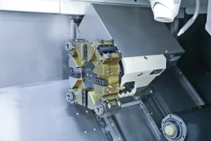
Programming CNC milling and turning is a complex process. Machining a new part requires multiple programming operations, such as CNC turning, multi-axis milling, 3+2 positioning, and drilling. This presents significant challenges in practice. Therefore, programming skills are typically reserved for highly experienced technicians. Even younger programmers with a solid foundation must possess advanced skills to independently complete a single programming task.
Programming with UGNX and CATIA
Using UGNX and CATIA, CNC milling and turning can be performed through dedicated programming modules.
- When roughing inverted surfaces, inclined walls, and contoured cavities, solids, surfaces, or curves can be selected to define the machining area, removing the majority of stock material.
- This method is suitable for roughing all external profiles and internal cavities of inverted parts.
- During roughing, a follow-the-part machining strategy is employed, generating toolpaths offset by a consistent stepover distance along the part’s geometric boundaries.
- When toolpaths intersect, the excess portion is automatically trimmed.
This strategy effectively removes unnecessary material around the part, making it particularly suitable for machining cavities.
Challenges in Complex Surface Machining
Complex curved surfaces, characterized by irregular shapes and large slope variations, introduce unique machining difficulties:
- Cutting depth and width change continuously during 3-axis CNC machining, leading to unstable cutting forces.
- This instability accelerates tool wear and reduces machining quality.
- Tool–workpiece interference is more likely in areas with steep or rough surfaces, which may cause serious machining errors.
Advantages of 3+2 Positioning
3+2 positioning machining overcomes the limitations of conventional 3-axis machining for complex surfaces:
- The B and C axes are rotated to specific viewpoints and locked before machining.
- After completing one machining area, the viewpoint of the B and C axes is readjusted according to the normal vector direction of the next area.
- CNC milling then continues from the new fixed viewpoint.
This essentially transforms five-axis machining into machining with a fixed axis orientation per setup, avoiding continuous tool axis direction changes during cutting.
Key advantages of 3+2 positioning:
- Higher machining efficiency.
- More consistent tool load.
- Improved surface quality compared with pure 3-axis CNC machining.
Thus, 3+2 positioning provides an effective solution for multi-axis milling and turning precision machining.
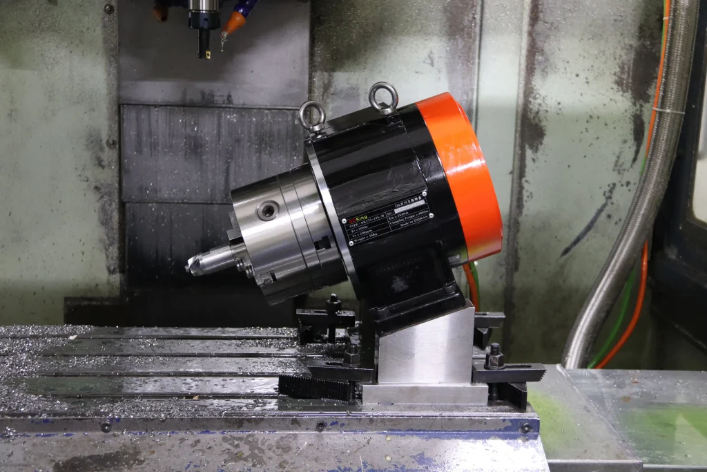
Practical Application in Multi-Axis Machining
Using multi-axis machining, we performed fine machining of multiple complex, fragmented surfaces on the cylindrical portion of an inverted part. The workflow involved:
- Selecting machining geometry.
- Defining tool drive modes.
- Setting related cutting parameters.
During actual machining, operators should:
- Fully utilize the machine’s kinematic characteristics.
- Control the tool’s swing angle changes to ensure a good match between displacement and rotation.
- Avoid overcutting by carefully coordinating linear and angular motions.
At sharp part corners:
- Appropriately add transition tool positions to reduce sudden swing angle changes.
- This helps maintain stable machine operation, prevent overcutting, and improve the surface finish of the machined part.
In summary, programming for CNC milling and turning requires deep technical expertise, precise software application, and optimized machining strategies. Among these, 3+2 positioning plays a vital role in bridging the gap between 3-axis and full 5-axis machining, delivering significant improvements in both efficiency and quality.