Introduction: An Overview of CNC Machining for Optical Mounts
In high-tech industries such as precision instrumentation, medical devices, and aerospace engineering, optical systems play a mission-critical role. However, system performance depends not only on the quality of optical components, but also on the precision, rigidity, and stability of the mounts that support them.
At Rapidefficient, we specialize in high-precision CNC machining solutions that ensure optical systems perform reliably under demanding conditions.
Why Are Optical Mounts So Important?
Optical mounts—often referred to as optical fixtures—act as the structural backbone of an optical system. Their core functions include:
- Precise Positioning: Ensuring accurate alignment of optical components according to optical path design. Even micron-level deviations can lead to image distortion or system failure.
- Long-Term Stability: Maintaining alignment despite vibration, thermal expansion, and environmental fluctuations.
- Component Protection: Supporting delicate optical elements without introducing stress or deformation.
A high-quality mount must therefore combine tight tolerances, excellent surface finish, and structural integrity.
How Does CNC Machining Enhance Mount Performance?
Traditional machining methods often struggle to meet modern optical requirements. CNC machining addresses these limitations through digital control, automation, and repeatability, enabling:
- Complex geometries with tight tolerances
- High consistency across batches
- Stable and repeatable production quality

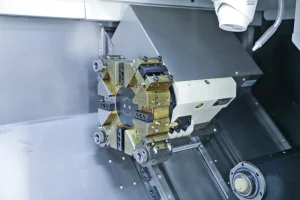
What Exactly Is CNC Machining for Optical Mounts?
CNC machining is a subtractive manufacturing process that starts from a solid block (aluminum, stainless steel, titanium, etc.). Using CAD/CAM-driven programs, cutting tools precisely remove material to achieve the final geometry.
At Rapidefficient, this process is optimized to ensure precision, stability, and manufacturability.
Why Choose CNC Machining for Optical Mounts?
Exceptional Precision
Optical systems typically require micron-level tolerances. CNC machining can reliably achieve ±0.01 mm or better, ensuring alignment accuracy.
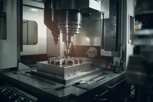
Complex Geometry Capability
Using 3-axis to 5-axis machining, complex structures such as cavities, curved surfaces, and lightweight designs can be manufactured in a single setup.
High Consistency
Program-controlled machining ensures every part meets identical specifications—critical for optical systems.
Core Technologies in CNC Machining for Optical Mounts
CAD/CAM Integration
Seamless CAD/CAM workflows reduce errors and improve efficiency, ensuring accurate translation from design to production.
Multi-Axis Machining
5-axis machining enables:
- One-setup processing
- Reduced repositioning errors
- Higher precision and efficiency
Precision Inspection
At Rapidefficient, all parts undergo strict quality control using:
- CMM (Coordinate Measuring Machines)
- Optical inspection systems
Advantages of CNC Machining for Optical Fixtures
High Precision and Repeatability
CNC systems use servo control and feedback systems to maintain consistent accuracy across batches.
Complex Structure Integration
Lightweight yet rigid designs—such as thin walls with internal ribs—can be machined in one piece.
Material Flexibility
Compatible materials include:
- Aluminum (6061, 7075)
- Stainless steel (304, 316L)
- Titanium alloys
- Invar and Kovar
Challenges and Professional Solutions
Material Stress and Deformation
Challenge: Internal stress release during machining can cause deformation.
Solution at Rapidefficient:
- Rough machining → stress relief → finish machining
- Controlled process strategy to maintain dimensional stability
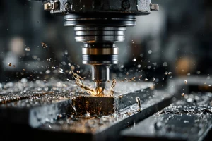
Tool Wear
Challenge: Tool wear affects precision and surface finish.
Solution:
- Advanced coated tools
- Real-time tool monitoring
- Automatic tool replacement
Application Scenarios
Medical Devices
Used in microscopes, endoscopes, and laser systems where alignment is critical.
Aerospace
Optical mounts must withstand extreme conditions such as:
- Launch vibration
- Temperature variation
Scientific Research
Applications include:
- Laser interferometers
- Spectrometers
- Particle accelerators
Case Study: Custom Optical Mount Solution
A Rapidefficient client required a high-power laser mirror mount with:
- High positioning accuracy
- Efficient heat dissipation
Our Solution:
- Material: Oxygen-free copper
- Structure: Integrated micro-channel cooling (5-axis CNC)
- Surface Treatment: Precision grinding + coating
Result: Improved thermal management and long-term system stability.

How to Choose the Right CNC Machining Partner?
Technical Capability
- 3-axis & 5-axis machines
- Experience with optical components
Quality Control
- CMM inspection
- Process standardization
Engineering Support
At Rapidefficient, we also provide:
- DFM optimization
- Material selection advice
- Cost-reduction strategies
Lead Time Consideration (已修正外贸逻辑)
For international projects, typical lead times are:
- Prototype: ~3–7 days
- Small batch: 1–3 weeks
Lead time depends on:
- Complexity
- Material availability
- Quantity
Rapidefficient ensures reliable scheduling and stable delivery, rather than unrealistic short timelines.
Conclusion
CNC machining has become essential for manufacturing precision optical mounts due to its advantages in:
- Accuracy
- Consistency
- Design flexibility
- Material compatibility
Partnering with an experienced manufacturer like Rapidefficient ensures your optical components meet the highest performance standards while maintaining cost efficiency and reliability.