I. Choosing the Right Material Eliminates the Risk of Later Defects
For this component, we initially had two material options for comparison:
First, 45 steel (normalized): Absolutely the king of cost-effectiveness! Excellent machinability, suitable for medium-load applications (such as automated equipment connections), and RoHS certified;
Second, SAE 4140 high-strength alloy steel: This material has a tensile strength of 900MPa, resistant to heavy loads and impacts. It is frequently used in automotive engines and heavy machinery, and will not deform due to high-frequency vibration.
Comparing the two, we chose SAE 4140 (quenched and tempered) because after quenching and tempering, it combines strength and impact resistance, has low residual stress, and is not easily deformed.
II. CNC Machining: Engraving the Precision of the Drawing into Every Tool Mark .
This seemingly ordinary disc is actually a culmination of 10 years of CNC experience—we created it as a troubleshootable part in 5 steps:
First, Digital Simulation: Importing the client’s 3D drawing into SolidWorks, we focused on optimizing the distribution angle of the small holes on the edges, while simulating the connection between the central hole and the arc-shaped groove. This ensures that there will be no “burr jamming” issues during machining.
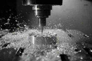
Second, Rough Machining: Using a Haas VF-3 CNC milling machine, equipped with a φ12mm carbide end mill, we rough milled at 1000rpm—leaving a 0.4mm finishing allowance, ensuring efficiency while preventing warping of the disc due to a “one-cut” operation.
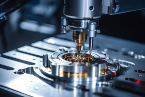
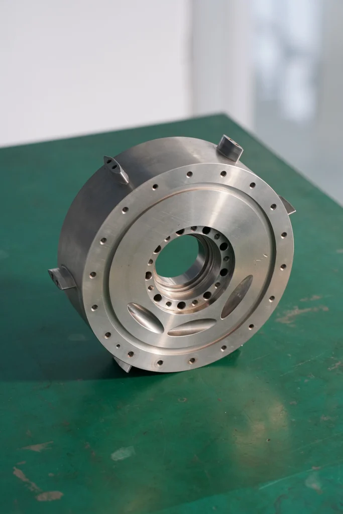
Third; Precision Machining: A five-axis CNC machine tool is used with φ8mm ceramic-coated cutting tools (high temperature resistant, wear-resistant) at high speed with slow feed. Eight evenly distributed M6 holes along the edge ensure a positional accuracy of ±0.01mm, directly matching standard bolts without secondary enlargement. A ring of six Φ10 holes around the center ensures a diameter tolerance of ±0.008mm, allowing for precise connection to drive shafts or pipe flanges. Small protrusions on both sides (3mm high) are formed in one piece, increasing rigidity by 30% and preventing vibration deformation.
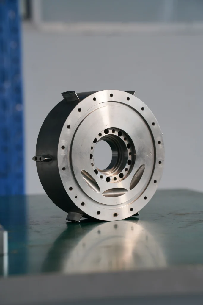
Fourth, Surface Treatment: Vibratory polishing removes all burrs, followed by optional hard anodizing (black/silver)—achieving a surface hardness of HV300, wear-resistant and scratch-resistant, preventing scratches to workers or adjacent parts during assembly.
Fifth, Full Inspection: At this stage, a Hexagon coordinate measuring machine scans all critical dimensions, accompanied by an SGS material report—for example, the height difference of the bottom support feet is <0.02mm, ensuring stable placement on the machine frame.
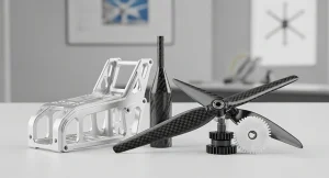
III. Functions and Applications
The core functions of this part are: precise positioning + stable connection + auxiliary functions (flow guidance/reinforcement), solving three of the most troublesome problems in industrial equipment: misalignment of connectors, wasting time on repeated adjustments; deformation under heavy loads, leading to equipment failure; and poor lubrication/flow guidance, accelerating wear.
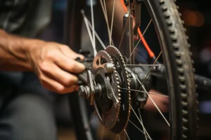
Below is a real-world example for reference: In a car factory in Michigan, USA, this part was used in the engine-transmission connection. Initially, the customer encountered a problem with previously purchased parts: uneven flange hole positions caused unbalanced torque transmission, resulting in loosening after 10,000 kilometers.
To address this, we developed a solution: using our multi-hole flange—its structural features include uniformly spaced small holes at the edges to transmit torque, a central hole to connect to the drive shaft, and an arc-shaped groove to guide engine oil.
Later, the verification results showed: no loosening after 100,000 kilometers of operation, and the scrap rate decreased by 18%, leading the factory to adopt it as a “standard connector.”
The customer chose us as their supplier for this part because:
First, it saves design time: we provide free DFM (Design for Manufacturability) analysis—if your drawings have areas that are difficult to machine (such as holes that are too close together), we will tell you in advance how to modify them, so you don’t have to wait until after mold opening for rework;
Second, small batch production is also possible: we support trial production of 5-500 pieces with very short lead times;
Finally, quality assurance: each batch of goods comes with a CMM (Chemical Modeling) dimensional report and material certificate, and key dimensions such as hole positions and support leg heights can be traced back to the machine tool used for machining—procurement no longer needs to worry about receiving the wrong product.