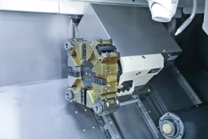
In CNC 4-axis machining, improving efficiency and ensuring quality require a coordinated effort across multiple aspects, including process planning, programming optimization, equipment debugging, and tool management, while also balancing machining stability and precision control. The following are specific methods:
CNC 4-axis Machining
1. Process Planning: Improving Efficiency and Quality from the Start
Optimize Process Integration and Reduce Setups
- Leverage the 4-axis’s “multi-surface machining in one setup” capability to integrate multiple processes (milling, drilling, chamfering, and tapping) into the same program.
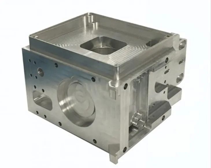
- Example: when machining a box part with an inclined hole, the A-axis can be rotated to sequentially machine the front, side, and inclined surfaces, avoiding the positioning errors caused by multiple setups in 3-axis machining.
- (Reducing the number of setups by one increases efficiency by 20%-30%, and achieves better dimensional consistency.)
Reference Surfaces and Locating Holes
- Prioritize machining of reference surfaces and locating holes, using them as a reference for subsequent machining.
- Ensures positional accuracy of each feature (such as the perpendicularity of the inclined hole to the plane) (error ≤ 0.01mm).
- Rationally divide the roughing and finishing stages.
Roughing
- High feed rates and large depths of cut (3-5mm, 1000-2000mm/min feed).
- Use high-speed steel or coated carbide tools (e.g., TiAlN-coated end mills).
- Use A-axis rotation to adjust the workpiece angle to avoid tool-workpiece interference.
Finishing
- Smaller depth of cut (0.1-0.3mm), high speed (8000-15000rpm).
- Use high-precision tools (ball end mills, boring tools).
- Enable the machine’s “high-precision mode” (e.g., “Contour Adaptive Control” on Siemens systems).
- Ensure contour accuracy (error ≤ 0.005mm) and surface roughness (Ra ≤ 1.6μm).
2. Programming and Toolpath Optimization: Reducing Backlash and Interference
Efficient 4-Axis Toolpath Design
- Use spiral or circular toolpaths instead of reciprocating toolpaths.
- For curved surfaces (e.g., impeller blades), spiral toolpaths reduce tool lift times (by 30%) and provide stable cutting forces, preventing surface marks.
Optimize Rotary Axis (A/B) Motion
- Avoid frequent direction changes (e.g., A-axis rapidly switching from +30° to -30°).
- Use “smooth transition” in CAM software (e.g., UG) to gradually change rotation angle, reducing vibration.
- For high-precision workpieces, surface roughness Ra reduced by 0.4-0.8μm.
Safe Height and Feed Method
- Roughing: safe height 5-10mm.
- Finishing: safe height 2-3mm.
- Use circular or oblique feeds to avoid tool impact from vertical cuts (extend tool life by 20%).
Interference Check and Simulation Verification
- After programming, use CAM 3D simulation to check interference between tool, toolholder, fixture, and workpiece.
- Example: turbine disks—ensure toolholder does not collide with hub at extreme A-axis angles.
- For batch production: test cut 1–2 parts, measure critical dimensions, then fine-tune parameters.
3. Equipment and Tooling: Ensuring Stability and Accuracy
Machine Tool Parameter Calibration and Optimization
- Regularly calibrate rotary axis positioning accuracy and repeatability.
- Use laser interferometer: positioning error ≤ 0.005mm/360°, repeatability ≤ 0.002mm.
- Adjust servo parameters based on material (shorter acceleration for aluminum, longer for steel).
- Enable “feedforward control” to reduce following error.
Thermal Error Compensation
- For long machining times (>8 hours), enable thermal error compensation.
- Reduces errors in long shafts by 50%.
Fixture Design and Workpiece Clamping
- Fixtures must be lightweight and rigid (within 60% of rotary axis load).
- Use ribs to increase rigidity (≤ 0.001mm/100N).
- Shafts: 3-jaw chuck + center combo (coaxiality ≤ 0.003mm).
- Special-shaped parts: custom tooling (e.g., blade fixture “one-face, two-pin” positioning ≤ 0.005mm).
- Avoid over-positioning and excessive clamping force (prevents deformation).
4. Tool Selection and Cutting Parameters: Balancing Efficiency and Life
Tool Matching
- Roughing: trowel milling cutter or face milling cutter (multi-edge, 10-16mm dia. for <100mm workpieces).
- Finishing: ball-end milling cutter (R angle = min curvature radius) or bullnose cutter (reduces tip wear).
- Bevel hole machining: high-speed steel or solid carbide drill with guide edge.
- Deep holes (>3×D): use peck drilling.
Cutting Parameters (45 steel example)
- Rough milling: VC = 100-150 m/min, fz = 0.1-0.2 mm/tooth, ap = 3-5 mm.
- Fine milling: VC = 150-200 m/min, fz = 0.05-0.1 mm/tooth, ap = 0.1-0.3 mm.
- Aluminum: increase to VC = 300-500 m/min.
- Titanium alloys: reduce to VC = 30-50 m/min.
Coolant
- Use high-pressure coolant (10-20 bar).
- Especially for stainless steel and titanium alloys.
- Reduces tool temp (extends life by 30%) and flushes chips.
5. Quality Inspection and Process Monitoring: Promptly Identify Problems
Online Inspection and Compensation
- Workpiece probe (e.g., Renishaw OMP40-2) checks dimensions after roughing, before finishing.
- Automatic correction of tool length or rotary axis angle (accuracy up to 0.001mm).
- For curved parts: laser profiler measures contour accuracy, adjusts toolpath dynamically.
Tool Condition Monitoring
- Sonar or vibration sensor monitors tool vibration (100-500Hz normal).
- Abnormal frequency → alarm + auto shutdown.
- Batch production: check tool wear every 50–100 parts.
- Replace if flank wear > 0.3mm.
6. Efficiency Improvement Techniques for Mass Production
Program Preview and Breakpoint Resume
- CNC “Program Preview” (e.g., FANUC AI Advanced Preview) analyzes 100–200 toolpath segments in advance.
- Makes motion smoother, increases feed speed 10%-15%.
- Breakpoint saving: resume from stop point, avoiding repeat machining (saves 20%-50%).
Automation Integration
- Robotic loading/unloading: reduces handling time (30–60s → 10–15s).
- Quick-change fixture system (e.g., EROWA): changeover time reduced (30 min → 5 min).
- Suitable for high-mix, small-batch production.