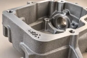
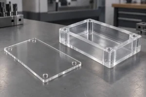
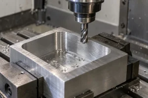
A CNC-machined heat sink is a custom thermal component produced by removing material from a solid plate, block, extrusion, or other suitable blank.
CNC machining is useful when a heat sink needs more than a standard fin profile. The same part may also include:
- A precision component-mounting surface
- Threaded holes and inserts
- Datum-related mounting holes
- Pockets for electronic modules
- Sensor or connector locations
- Sealing faces
- Integrated enclosure walls
- Local copper inserts
- Features on several sides
However, CNC machining is not automatically the best process for every high-power cooling application. Standard extrusions, skived fins, bonded-fin assemblies, die casting, heat pipes, vapor chambers, or liquid cold plates may provide a better balance of performance, volume, weight, and cost.
The manufacturing route should follow the thermal system—not the assumption that more machining always creates a better heat sink.
A Heat Sink Is a Thermal Path, Not Just a Set of Fins
A heat sink only works when heat can travel through the complete assembly:
Heat source → thermal interface material → heat sink base → fin structure → surrounding air
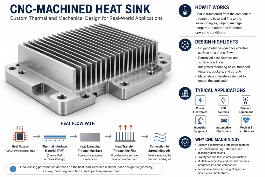
The thermal interface is important because two apparently smooth surfaces still contain microscopic gaps. Thermal grease, pads, films, or other interface materials fill part of this air space and reduce contact resistance between the device and heat sink.
The base then performs two jobs.
First, it receives heat from the component. Second, it spreads that heat over a larger area so that more of the fin structure can participate in cooling. A highly conductive material cannot compensate for a poor interface, a base that is too flexible, or fins that receive little useful airflow.
This is why the drawing should not begin with an isolated statement such as:
Base flatness must be 0.02 mm.
Instead, the requirement should come from:
- Heat-source size and location
- Contact area
- Thermal interface material
- Mounting pressure
- Base dimensions
- Heat load
- Assembly structure
- Inspection area and support condition
A small contact pad and a large machined enclosure do not need the same flatness definition or inspection method.
Where CNC Machining Earns Its Place
The best heat sink process depends on quantity, geometry, fin requirements, thermal targets, tooling cost, and the amount of secondary machining.
| Manufacturing route | Where it usually works well | Main limitation to review |
|---|---|---|
| Extrusion | Long profiles, repeat production, conventional parallel fins | Cross-section is largely fixed along the extrusion direction |
| CNC machining | Custom geometry, prototypes, low volume, integrated mounting and enclosure features | Material removal, cycle time, tool access, and thin-fin stability |
| Skived fins | Thin, dense fins in aluminum or copper | Fin handling, available geometry, and follow-up machining |
| Bonded or brazed fins | Large bases, tall fins, high surface area, mixed materials | Fin-to-base joining method and assembly control |
| Die casting | Higher volumes and integrated housings | Tooling investment, section limits, porosity, and final machining |
| Liquid cold plate | High heat flux or limited air-cooling capacity | Sealing, fluid connections, pressure drop, and leak testing |
Skived heat sinks can provide fin densities beyond many extrusion designs, while bonded-fin construction allows tall or numerous fins to be attached to an extruded or machined base. These alternatives can outperform a fully machined-from-solid design when the required fin structure would make CNC removal inefficient or fragile.
CNC machining is especially valuable when the thermal part must combine cooling with mechanical functions, such as:
- A heat sink integrated into an electronics enclosure
- Precisely located power modules
- Sealing grooves around a cooled cavity
- Multiple component contact pads at different heights
- Threaded mounting features
- Connector cutouts
- Internal pockets
- Low-volume design changes
It is also useful for machining mounting faces, holes, slots, and component pockets into an existing extrusion, casting, or skived-fin blank. The decision is therefore not limited to “fully CNC machined” versus “not CNC machined.”
Four Geometry Decisions Control the Result
The Base and Thermal Interface
The base must transfer heat from the source and distribute it toward the fins.
A very thin base may reduce weight, but it can also:
- Spread heat poorly away from a concentrated source
- Deflect under mounting pressure
- Move during machining
- Distort after unclamping
- Become difficult to inspect consistently
A thicker base may improve spreading and rigidity, but it also adds mass, material, and sometimes unnecessary thermal path length.
The correct design should define:
- Contact area
- Base thickness
- Component position
- Mounting pattern
- Required flatness area
- Surface condition
- Thermal interface material
- Clamping method
Surface roughness and flatness should be reviewed together. A smoother surface does not fix a warped base, while a flat base may still require a suitable TIM to reduce microscopic interface gaps.
Fin Thickness, Height, and Spacing
Adding more fins increases surface area, but it also reduces the space available for airflow.
Closely spaced fins may create higher pressure drop or encourage air to bypass the fin channels. Under natural convection, overly dense fins can restrict the movement of warm air. Under forced convection, the fin layout must match the available fan pressure and the actual flow path through the enclosure.
The practical design must balance:
- Fin surface area
- Channel spacing
- Fin length
- Fin height
- Airflow direction
- Fan pressure
- Dust and contamination risk
- Machining access
- Fin stiffness
For CNC machining, the cutter must also enter and clear each channel. Fin spacing that looks reasonable in a thermal model may require an excessively long or small-diameter tool.
Mounting Holes and Heat-Source Location
A heat sink can have a flat base and still assemble poorly if the mounting pattern is misplaced.
Hole position affects:
- Contact pressure
- TIM compression
- Alignment with the heat source
- Fastener load
- Connector clearance
- Sealing
- Module replacement
The drawing should use functional datums instead of locating critical holes from several unrelated exterior edges.
Where several power devices share one base, their height, position, clamping method, and interface material must also be considered together. A single machined plane may not contact every component correctly when stack-up variation is ignored.
Airflow and Enclosure Integration
The fins must work with the actual airflow direction.
A fin array can perform well in an isolated test and poorly inside a crowded enclosure because air may:
- Bypass the fins
- Enter at an angle
- Recirculate near the outlet
- Be blocked by cables or boards
- Receive preheated air from another component
- Accumulate dust in narrow channels
Heat sink geometry, fan selection, pressure drop, and enclosure layout should therefore be reviewed as one system.
How a CNC Heat Sink Is Machined Without Losing Its Shape
A stable heat sink is usually produced through a controlled sequence rather than by cutting every feature to final size in one setup.
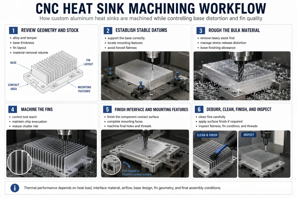
1. Review the Stock and Thermal Design
Before programming, confirm:
- Aluminum grade and temper
- Blank type
- Material-removal percentage
- Base thickness
- Fin geometry
- Contact surfaces
- Mounting features
- Final finish
- Inspection condition
A large block with deep material removal behaves differently from a near-net extrusion that only needs mounting and interface features.
2. Establish Stable Datums
The first operations should create reliable locating surfaces for later setups.
The fixture must support the part without forcing a flexible base into an artificially flat condition. Otherwise, the part may pass inspection while clamped and move after release.
3. Rough the Heavy Sections Before Finishing Critical Faces
Large pockets and deep material removal can release residual stress.
Where geometry requires it, the process may separate:
- Heavy roughing
- Intermediate unclamping or stabilization
- Secondary roughing
- Fin machining
- Final base finishing
The exact sequence depends on stock condition, geometry, quantity, and tolerance.
4. Machine the Fins With Controlled Engagement
Tall, thin fins behave like flexible walls.
Common risks include:
- Chatter
- Fin deflection
- Inconsistent thickness
- Burrs
- Tool rubbing
- Chip packing
- Damage during cleaning or handling
A shorter, more rigid cutter is preferable where geometry permits. Stable engagement, controlled stepdown, suitable flute space, and reliable chip evacuation matter more than simply increasing spindle speed.
5. Finish the Thermal Interface Late in the Process
Final machining of the component-mounting surface is often scheduled after major material removal.
This reduces the chance that later roughing operations will change:
- Flatness
- Parallelism
- Step height
- Contact-pad position
- Surface condition
The inspection must specify the measured area and whether the part is supported, free, assembled, or restrained.
6. Deburr and Clean Without Damaging the Fins
Loose chips and burrs can interfere with airflow, assembly, electrical clearance, and surface treatment.
Thin fins should be handled carefully during:
- Deburring
- Ultrasonic or aqueous cleaning
- Internal transport
- Anodizing
- Inspection
- Packaging
Fin damage after machining can be just as important as the cutting process itself.
Why Heat Sink Bases Warp and Fins Chatter
Base distortion and fin vibration are related to different parts of the same stiffness problem.
Base Distortion
A base may move because of:
- Residual stress in the stock
- Uneven stock removal
- Excessive clamping
- Thin remaining sections
- Heat accumulation
- One-sided machining
- Inadequate support
- Stress released after unclamping
A universal flatness number does not solve these risks. The supplier must know the controlled area, the base size, the assembly interface, and the inspection condition.
Fin Chatter
Fin chatter is more likely when the design combines:
- Tall fins
- Low fin thickness
- Narrow channels
- Long tool projection
- Changing engagement
- Poor chip removal
- Weak base support
A finer finishing pass cannot always remove chatter if the fin moves away from the cutting edge. The correction may require a different toolpath, support strategy, cutter, engagement, fin geometry, or manufacturing route.
Where a thermal design requires extremely thin and dense fins, skiving or bonded-fin construction may be more practical than milling every channel from a solid block.
Material Choice Is More Than Thermal Conductivity
Higher thermal conductivity is useful, but it is not the only material requirement.
A CNC heat sink may also need:
- Thread strength
- Flatness stability
- Corrosion resistance
- Low weight
- Cosmetic anodizing
- Structural mounting
- Repeatable material supply
- Practical machining time
6061-T6 is widely considered for machined cooling components because it provides a useful balance of thermal performance, strength, availability, machinability, and finishing response.
6063 is strongly associated with extruded heat sink profiles, while higher-conductivity aluminum grades may be useful when heat spreading is the dominant requirement and the design can accept lower strength or different manufacturing behavior.
Copper provides higher conductivity but also adds weight, cost, and machining considerations. Some assemblies use copper only near the concentrated heat source and aluminum for the larger structure.
For a detailed alloy comparison, review our guide to aluminum alloys for heat dissipation.
Anodizing, Masking, and the Contact Surface
Anodizing converts the aluminum surface into an integrated oxide finish rather than applying a separate layer like paint. It can improve corrosion resistance, wear behavior, appearance, and surface emissivity.
A dark anodized surface may increase the radiative contribution to cooling, particularly where radiation is meaningful relative to convection. It should not be treated as a guaranteed substitute for adequate airflow or fin design.
The drawing should clearly identify:
- Cosmetic surfaces
- Component contact pads
- Grounding areas
- Threads
- Fitted holes
- Sealing faces
- Areas requiring masking
- Dimensions that apply after anodizing
The base does not always need to remain completely bare. The correct treatment depends on the TIM, electrical requirements, corrosion exposure, mounting method, oxide specification, and final dimensional requirement.
For masking, dimensional change, cosmetic control, and finish selection, review our surface finishes for CNC-machined parts.
Inspect the Features That Control the Thermal Assembly
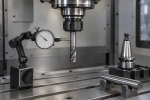
Dimensional inspection cannot directly prove that a heat sink will meet its thermal target. It verifies whether the manufactured part matches the drawing and assembly requirements.
A practical inspection plan may include:
- Base flatness over a defined area
- Contact-pad height or step
- Mounting-hole position
- Thread acceptance
- Fin thickness and spacing
- Fin damage
- Burr condition
- Post-anodize dimensions
- Surface roughness where specified
- Part cleanliness
- Cosmetic finish
Possible inspection methods include:
- Surface plate and indicator
- Height gauge
- CMM
- Micrometer
- Pin or thread gauges
- Roughness tester
- Optical inspection
- Functional assembly check
Thermal resistance, temperature rise, or airflow performance requires a separate functional test under defined operating conditions. A dimensional report should not be presented as a replacement for thermal validation.
The Best CNC Heat Sink Starts With the Assembly
A successful CNC heat sink drawing should describe more than the fin count.
Before quotation, the supplier should understand:
- Heat-source location
- Heat load and service conditions
- Airflow direction
- Thermal interface material
- Component-mounting method
- Critical contact surfaces
- Base and fin geometry
- Aluminum grade and temper
- Anodizing and masking
- Quantity
- Inspection requirements
CNC machining makes the most sense when custom geometry, integrated mechanical features, mounting accuracy, prototype speed, or low-volume flexibility creates real value.
It should not be chosen simply because the application produces a large amount of heat.
Rapid Efficient supports custom heat-dissipation parts, machined enclosures, thermal bases, and integrated aluminum housings. Send the 2D drawing, 3D model, material, quantity, finish, and inspection requirements for review through our CNC aluminum machining services.