Quick Answer: What Should Buyers Check in a CMM Report?
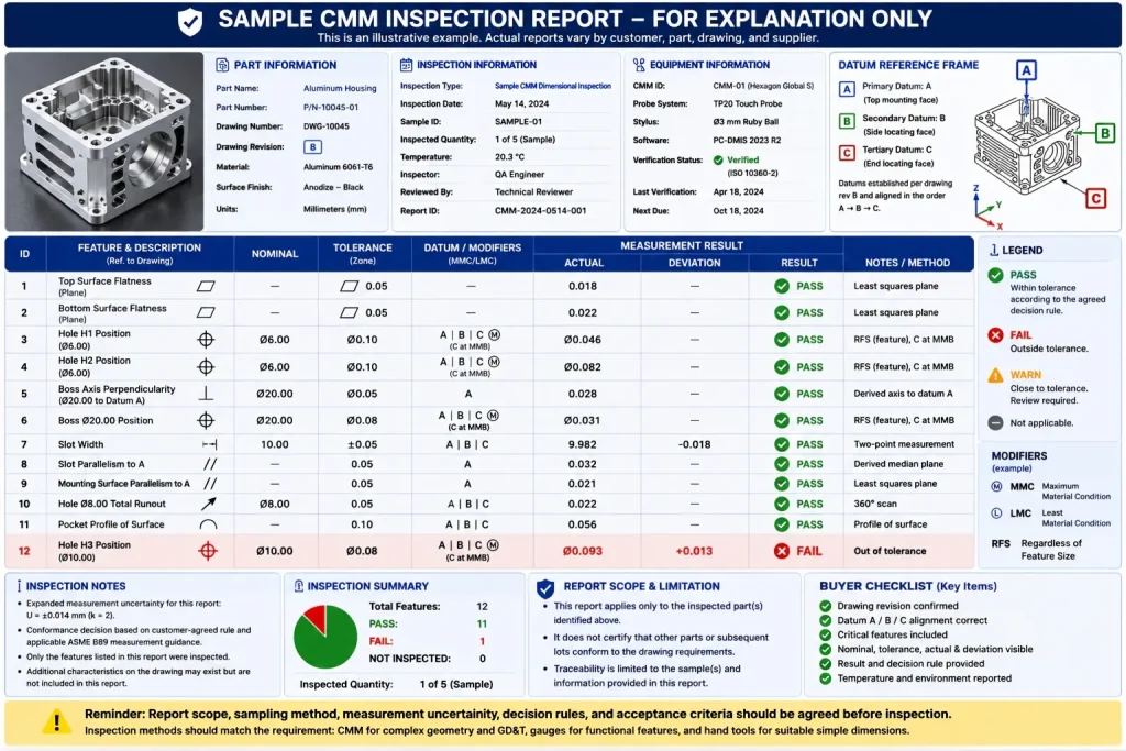
A useful CMM inspection report should show more than a green PASS result.
Buyers should confirm:
- Correct part number and drawing revision
- Measurement units
- Inspected part or sample identification
- Datum A, B, and C alignment
- Critical feature IDs
- Nominal values and tolerance limits
- Actual measured values and deviations
- GD&T controls and material-condition modifiers
- Inspected quantity and report scope
- Measurement temperature when relevant
- Equipment and calibration or verification status when required
- The agreed PASS/FAIL decision rule
CMM inspection is especially useful for parts with position tolerances, profiles, multiple related bores, sealing faces, bearing locations, complex datum structures, or several machining setups.
It is not automatically necessary for every dimension. Calipers, micrometers, bore gauges, pin gauges, thread gauges, roughness testers, and other instruments may be more appropriate for certain features.
A CMM report verifies only the inspected parts and features. It does not prove that the complete production batch is conforming unless the inspection scope, sample plan, and process controls support that conclusion.
Rapid Efficient can review the drawing and coordinate CMM inspection and dimensional reports when the project requires them. The report scope, inspected quantity, format, and cost should be confirmed before quotation.
CMM Report Buyer Checklist
| Report Item | Why It Matters | What the Buyer Should Check |
|---|---|---|
| Part identity | Prevents the wrong part or report from being accepted | Part number, serial number, lot, or inspected sample ID |
| Drawing basis | Ensures the inspection follows the correct requirement | Drawing revision, units, general tolerances, and applicable GD&T standard |
| Inspection scope | Shows what the report actually proves | Inspected features, inspected quantity, sample plan, and excluded characteristics |
| Datum alignment | Controls how the part coordinate system is established | Whether Datum A, B, and C follow the drawing sequence and functional setup |
| Feature identification | Connects the report to the drawing | Balloon number, feature ID, or clear callout reference |
| Nominal and tolerance | Defines the acceptance zone | Nominal value, upper and lower limits, or geometric tolerance zone |
| Actual result | Shows the measured condition | Actual value, deviation, and result for every critical feature |
| GD&T interpretation | Prevents incorrect evaluation | Position, profile, flatness, perpendicularity, runout, and applicable modifiers |
| Decision rule | Controls how PASS or FAIL is assigned | Whether measurement uncertainty or guard banding is considered when required |
| Equipment status | Supports confidence in the measurement system | Equipment ID and current calibration or performance-verification status |
| Measurement strategy | Affects the calculated feature result | Probe type, point distribution, scanning strategy, filters, and fitting method when critical |
| Environment | Helps explain temperature-sensitive results | Part temperature, room condition, stabilization, and thermal compensation when relevant |
| Report approval | Establishes traceability | Inspection date, inspector, reviewer, and report approval status |
What Is CMM Inspection?
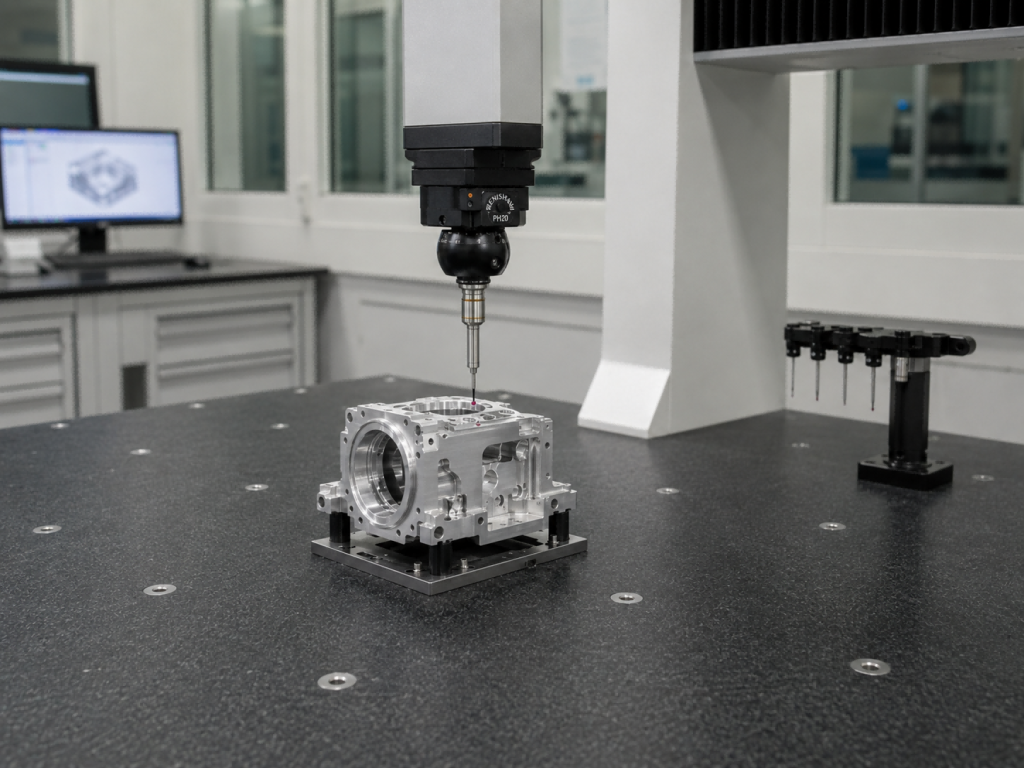
CMM stands for Coordinate Measuring Machine.
A CMM measures points on a component in three-dimensional space. Depending on the machine and inspection system, it may use:
- A touch-trigger probe
- A scanning probe
- An optical or vision sensor
- Another compatible non-contact sensor
The inspection software uses the measured points to construct features such as:
- Planes
- Circles
- Cylinders
- Lines
- Slots
- Spheres
- Cones
- Freeform profiles
A CMM can evaluate:
- Linear dimensions
- Bore diameter
- Hole and bore position
- Flatness
- Straightness
- Parallelism
- Perpendicularity
- Angularity
- Profile of a line or surface
- Circular or total runout
- Datum relationships
The result does not depend only on the machine’s advertised accuracy.
It can also be affected by:
- Part alignment
- Datum simulation
- Probe qualification
- Stylus length and stiffness
- Probe access
- Number and location of measured points
- Scanning speed
- Filtering
- Feature-fitting algorithm
- Part restraint
- Temperature
- Measurement uncertainty
A CMM is therefore a measurement system, not an automatic guarantee that every programmed result is correct.
Current ISO 10360 standards define acceptance and periodic reverification tests for CMM systems and probing configurations; machine performance and the actual part-measurement strategy are related but not identical questions.
Why CMM Inspection Matters for CNC Machined Parts
In precision CNC machining, a part can look correct but still fail in assembly.
For example:
- A bore diameter may be within tolerance, but its centerline may be shifted.
- A mounting face may look smooth, but its flatness may not meet the sealing requirement.
- A hole pattern may be acceptable individually, but its true position may fail relative to the datum.
- A thin-wall part may measure correctly during machining but deform after unclamping.
This is why CMM inspection is important. It checks the part as a functional geometry, not only as a collection of separate dimensions.
For buyers, a good CMM report provides evidence that the supplier understands the drawing, the datum structure, and the final assembly requirement.
Caliper, Gauge, and CMM Inspection Compared
| Inspection Method | Practical Use | Main Limitation |
|---|---|---|
| Caliper | Length, width, thickness, steps, and accessible diameters | Limited resolution and cannot reliably verify complex datum relationships |
| Micrometer | Accurate external or accessible thickness and diameter measurement | Measures isolated size rather than complete 3D feature relationships |
| Bore gauge | Bore size, taper, and out-of-round comparison | Requires setting standards and does not directly establish feature position |
| Pin or plug gauge | Fast functional verification of holes | Normally gives accept/reject information rather than a complete measured value |
| Thread gauge | Functional GO / NO-GO thread inspection | Does not provide a full thread-profile or location report |
| Height gauge and surface plate | Heights, basic positions, and orientation checks | Setup, access, reference surface, and operator method affect the result |
| Optical comparator or vision system | Profiles, edges, radii, and small two-dimensional features | Limited for hidden three-dimensional features and complex datum structures |
| CMM inspection | 3D geometry, position, profile, orientation, form, and datum relationships | Requires a valid program, suitable probing strategy, correct alignment, and adequate measurement capability |
| Surface roughness tester | Ra, Rz, and other specified surface-texture parameters | Measures surface texture rather than dimensional geometry |
Many CNC parts pass a quick caliper check but still fail during assembly. The reason is simple: calipers measure isolated sizes, while CMM inspection can verify geometry, position, and datum relationships.
A caliper may confirm that a hole diameter is correct. But it cannot reliably prove whether the hole is in the correct position relative to Datum A, B, and C.
For precision CNC parts, this difference matters.
CMM Report, Full Dimensional Report, and FAI Are Not the Same
CMM describes a measurement method. FAI and full dimensional inspection describe the scope of the inspection report.
| Report Type | What It Usually Includes | Important Boundary |
|---|---|---|
| Basic dimension report | Selected lengths, diameters, thicknesses, and simple features | May not include all critical GD&T or datum relationships |
| CMM report | Features measured with a coordinate measuring system | Does not mean every drawing characteristic was inspected |
| Full dimensional report | Measured results for all agreed drawing characteristics | May combine CMM, hand tools, gauges, roughness testing, and other methods |
| First Article Inspection | Initial verification of a new or changed manufacturing process | FAI is a reporting and approval scope, not a specific measuring instrument |
| Lot or sampling inspection report | Results for an agreed number of parts from a batch | Does not prove every part unless 100% inspection is specified |
| Capability study | Process data collected across multiple parts or production cycles | One CMM report cannot demonstrate process capability by itself |
Before ordering inspection, the buyer should define:
- Whether material and finish certificates are also needed
- Which drawing characteristics must be reported
- Whether the inspection is first-article, sampling, or 100%
- Whether raw or finished dimensions are required
- Whether surface treatment is included
- Which report template is required
Key CMM Inspection Items Buyers Should Review
1. Critical Dimensions
Critical dimensions directly affect assembly, performance, sealing, motion, or load-bearing function.
Examples include:
- Bearing bore diameter
- Mounting hole position
- Sealing face flatness
- Shaft center distance
- Threaded hole location
- Precision slot width
- Datum surface height
A CMM report should clearly show which dimensions were inspected and whether the measured values are within tolerance.
2. Datum Reference Frame
The datum reference frame establishes how the part is oriented and located for geometric inspection.
The physical fixture used to hold the part is not automatically the datum.
The CMM normally measures the specified datum features and uses them to simulate the primary, secondary, and tertiary datum references defined by the drawing.
Buyers should check:
- Whether Datum A, B, and C match the drawing
- Whether the datum precedence is correct
- Whether datum targets are used where specified
- Whether material-boundary modifiers are interpreted correctly
- Whether the part is measured restrained or in a free state
- Whether the fixture distorts a flexible component
- Whether the inspection alignment represents the functional assembly
Using a convenient outer edge instead of the defined datum may produce a clean-looking report that does not represent how the component will assemble.
For a deeper explanation of primary, secondary, tertiary, process, and inspection datums, review our guide to types of CNC machining datums.
3. Position Tolerance
Position tolerance—often informally called true position—controls the location of a feature relative to theoretically exact dimensions and, when specified, a datum reference frame.
Feature size and feature position are separate requirements.
A hole can have the correct diameter but still fail position. A hole can also meet position while its diameter is out of tolerance.
Position inspection is commonly used for:
- Bolt-hole patterns
- Locating-pin holes
- Bearing bores
- Connector interfaces
- Threaded-hole patterns
- Mating features
- Multiple related bores
A useful CMM report should show:
- Feature size
- Positional result
- Referenced datums
- Diameter tolerance-zone symbol when applicable
- MMC, LMC, or default RFS interpretation
- Any applicable bonus tolerance
- Datum material-boundary modifiers
- PASS/FAIL result under the agreed decision rule
The buyer should not accept a report that shows only a hole diameter when the drawing controls the hole’s position.
4. Flatness
Flatness controls whether a surface is sufficiently even.
This matters for:
- Sealing faces
- Mounting plates
- Heat sink contact surfaces
- Optical mounting surfaces
- Fixture bases
- Thin-wall housings
A part may look flat by eye, but a small surface deviation can create leakage, poor thermal contact, vibration, or assembly gaps.
For precision parts, flatness should be measured with the correct inspection method, not judged visually.
5. Coaxiality, Position, and Runout of Cylindrical Features
Cylindrical features may need to share a common axis, rotate without excessive variation, or remain correctly located relative to a datum axis.
The correct drawing control depends on the part function.
Possible controls include:
- Position of a bore or shaft axis
- Circular runout
- Total runout
- Cylindricity
- Perpendicularity of an axis
- Profile
- A customer-specific coaxial alignment requirement
Do not automatically label every axis-alignment requirement as concentricity.
For drawings using ASME Y14.5-2018, the concentricity and symmetry symbols were removed. Position, runout, or another appropriate control may be used depending on the design intent.
Older drawings or drawings prepared under another standard may use different terminology, so the CMM program must follow the standard and callout shown on the actual drawing.
Possible assembly problems caused by poor cylindrical alignment include:
- Bearing misalignment
- Shaft binding
- Excessive runout
- Vibration
- Uneven seal loading
- Noise
- Premature wear
The report should identify the exact controlled feature and reference, rather than showing a generic “concentricity” result without drawing context.
ASME’s own Y14.5-2018 supporting material confirms that concentricity and symmetry were removed from the 2018 revision.
Inspection Temperature and Part Stabilization
Dimensional specifications normally use a standard reference temperature of 20°C.
This does not mean that every CNC workshop or inspection room must remain at exactly 20°C at every moment. It means that temperature effects must be understood and controlled to a level suitable for the required tolerance and measurement uncertainty.
Important factors include:
- Part temperature
- CMM temperature
- Temperature gradients
- Material coefficient of thermal expansion
- Time allowed for stabilization
- Handling heat
- Recent machining or cleaning
- Thermal compensation settings
- Part size and geometry
As an illustrative example, a 100 mm aluminum feature may change by approximately 0.023 mm across a 10°C uniform temperature difference.
The actual result depends on the aluminum grade, temperature distribution, measurement timing, and compensation method.
For tight-tolerance parts, the report or inspection plan should state:
- Measurement temperature when relevant
- Whether the component was stabilized
- Whether thermal compensation was applied
- Which coefficient of thermal expansion was used
- Whether the acceptance decision accounts for measurement uncertainty
Temperature gradients can be more difficult than a uniform temperature offset because they may change the shape of the part, not only its overall size.
The current international reference-temperature standard is ISO 1:2022, which retains 20°C as the standard reference temperature. NIST also identifies temperature, thermal gradients, probing, fixturing, alignment, and compensation as contributors to dimensional-measurement uncertainty.
CMM Inspection and Tolerance Stack-Up
CMM inspection is also important for identifying tolerance stack-up risk.
Tolerance stack-up happens when small errors from datums, fixtures, machining deviation, thermal drift, and inspection alignment accumulate across multiple features.
A CMM report can help confirm whether the final feature relationships are still within the acceptable range.
For example, a part may have:
- One bore slightly shifted
- One mounting face slightly out of flatness
- One hole pattern slightly rotated
- One datum surface slightly distorted
Individually, these may look minor. But together, they can cause assembly failure.
For a deeper explanation, see:
CNC Machining Tolerance Stack-Up
Engineer’s Note: A Green PASS Result Is Not Enough
A CMM report is useful only when its inspection strategy matches the drawing and the part’s functional assembly.
The same physical component can produce different calculated results when the program changes:
- Datum alignment
- Point distribution
- Scanning path
- Feature-fitting method
- Filtering
- Outlier removal
- Probe configuration
- Part restraint
For bearing bores, sealing surfaces, locating holes, and mating features, the buyer and supplier should agree which surfaces establish the functional coordinate system.
A report can show green PASS results and still provide little confidence when:
- The wrong drawing revision was used
- Only non-critical dimensions were inspected
- The wrong datum was selected
- Too few points were measured
- The part was distorted by the fixture
- The report covers only one part but is treated as proof of the full batch
- A near-limit result ignores the agreed decision rule
Inspection planning should be connected to drawing review, fixture design, machining sequence, and final assembly requirements before production begins.
What a Good CMM Inspection Report Should Include
| Report Section | Recommended Information |
|---|---|
| Report identity | Report number, inspection date, report revision, and approval status |
| Part traceability | Part name, part number, serial number, lot, or inspected sample ID |
| Drawing basis | Drawing number, revision, units, general tolerances, and applicable GD&T standard |
| Material and finish | Material grade, temper or condition, and whether inspection occurred before or after finishing |
| Inspection scope | Feature list, inspected quantity, sample plan, and characteristics not included |
| Measurement equipment | Equipment ID, CMM type, probe or sensor configuration, and software when required |
| Equipment status | Current calibration or performance-verification status and applicable due date when contractually required |
| Datum alignment | Primary, secondary, and tertiary datums, datum targets, and restraint condition |
| Feature results | Feature ID, nominal value, tolerance, actual result, deviation, and PASS/FAIL |
| GD&T results | Position, profile, form, orientation, runout, and applicable material-condition modifiers |
| Measurement strategy | Point count, scanning, fitting, filtering, or other strategy when it materially affects the result |
| Environment | Part temperature, room condition, stabilization, and thermal compensation when relevant |
| Decision rule | How conformity is determined, including measurement uncertainty when required |
| Approval | Inspector, reviewer, signature, and any exceptions or concessions |
Not every standard shop report needs to display every item above.
The required report depth should match:
- Consequences of a false acceptance or false rejection
- Part risk
- Tolerance level
- Customer specification
- Contract requirement
- Industry requirement
- Inspection cost
Common CMM Report Mistakes Buyers Should Avoid
Mistake 1: Checking Only the Final PASS Result
Review which features were inspected, not only the color of the result.
Mistake 2: Ignoring the Drawing Revision and Units
A technically correct report can still be useless if it was created from an obsolete drawing or the wrong unit system.
Mistake 3: Ignoring Datum Alignment
A feature measured from a convenient edge may pass even though it fails relative to the functional datums.
Mistake 4: Treating One Inspected Part as Proof of the Entire Batch
The report should identify the inspected quantity and sampling method.
Mistake 5: Assuming CMM Is the Best Tool for Every Requirement
Threads, surface roughness, hardness, coating thickness, material composition, and some internal features may require other instruments.
Mistake 6: Ignoring Measurement Uncertainty Near the Limit
A result very close to a specification limit may require an agreed decision rule rather than a simple green PASS label.
Mistake 7: Confusing Machine Calibration With Part-Measurement Capability
A calibrated or verified CMM still requires a suitable program, probe, fixture, alignment, environment, and measurement strategy.
Mistake 8: Measuring Flexible Parts Under the Wrong Restraint
Thin walls and large plates may change after unclamping. The free-state or restrained inspection condition should be defined.
Mistake 9: Requesting CMM Inspection Too Late
Waiting until the full batch is complete can turn a programming or datum error into repeated scrap.
When Should Buyers Request CMM Inspection?
CMM inspection is worth considering when the part includes:
- Position or profile tolerances
- Multiple related bores or hole patterns
- Complex datum reference frames
- Bearing or locating features
- Sealing-face flatness
- Circular or total runout
- Large or flexible geometry
- Multiple machining setups
- Complex three-dimensional surfaces
- Features that are difficult to reach with hand tools
- High assembly or rework risk
- First-article approval
- A major drawing, tooling, supplier, or process change
Full CMM inspection may not be necessary for:
- Simple loose-tolerance brackets
- Basic cut lengths
- Easily accessible outside dimensions
- Functional threads better verified by thread gauges
- Surface roughness better verified by a profilometer
- Features that can be checked more reliably with dedicated gauges
The inspection method should match the characteristic rather than forcing every drawing dimension into one CMM program.
CMM Inspection Cost vs Project Risk
CMM inspection adds real project cost through:
- Inspection programming
- Probe setup and qualification
- Part fixturing
- Part stabilization
- Measurement time
- Report preparation
- Review and approval
- Repeat inspection after correction
Requesting a full CMM report for every dimension can therefore be unnecessary and expensive.
However, insufficient inspection can create larger downstream costs.
| Inspection Risk | Possible Result | Practical Control |
|---|---|---|
| Wrong drawing revision | Correctly measuring the wrong requirement | Confirm revision before programming |
| Critical features omitted | Assembly failure despite a passing report | Mark critical characteristics before quotation |
| Inspection performed only after the full batch | Repeated error across many parts | Use first-article approval before repeat production |
| One sample treated as proof of the lot | Undetected batch variation | Define sampling or 100% inspection |
| Wrong datum alignment | Report does not represent assembly function | Review datum setup before measurement |
| Near-limit result without decision rule | Supplier dispute or false acceptance | Agree how uncertainty is handled |
| Excessive CMM scope | Higher cost and lead time without added value | Use gauges or hand tools where more appropriate |
| No traceability | Report cannot be linked to the delivered parts | Record sample, lot, serial, or batch information |
The most cost-effective plan is normally risk-based:
Measure critical features early enough to correct the process.
Use CMM for complex geometric relationships.
Use gauges for high-volume functional features.
Use hand tools for suitable simple dimensions.
CMM Inspection Support for Custom CNC Parts
Rapid Efficient can review inspection requirements and coordinate CMM inspection when the drawing or project risk requires it.
Available inspection support may include:
- Critical feature identification
- Drawing and revision review
- Datum alignment planning
- Position and profile inspection
- Flatness and orientation checks
- Bore and axis relationship checks
- First-article dimensional reports
- CMM reports for agreed characteristics
- Material and surface-finish reports when requested
The RFQ should identify:
- Required drawing revision
- Critical dimensions and GD&T
- Datum structure
- Required report format
- Inspected quantity
- First-article, sampling, or full-inspection scope
- Material and finish condition
- Free-state or restrained measurement condition
- Required certificates
- Applicable decision rule or customer standard
CMM inspection and report availability depend on the component, tolerance, geometry, quantity, and agreed inspection scope.
FAQ: CMM Inspection for CNC Machined Parts
What Does a CMM Measure?
A CMM measures coordinates on a component and uses them to calculate features such as planes, circles, cylinders, slots, profiles, and datum relationships.
It can evaluate size, position, form, orientation, profile, and runout when the machine, probe, program, and measurement strategy are suitable.
Is CMM Inspection Necessary for Every CNC Part?
No.
Simple dimensions may be inspected more efficiently with calipers, micrometers, bore gauges, pin gauges, or functional gauges.
CMM inspection is most valuable for complex geometry, GD&T, related features, difficult access, or high assembly risk.
What Should a Buyer Check in a CMM Report?
Check the part identity, drawing revision, units, inspected quantity, datum setup, critical feature IDs, nominal values, tolerances, actual results, deviations, PASS/FAIL method, environment when relevant, and report approval.
What Is the Difference Between a CMM Report and First Article Inspection?
A CMM report identifies results produced by a coordinate measuring system.
First Article Inspection defines an initial approval scope and may combine CMM results with hand-tool measurements, gauges, material certificates, finish certificates, and other documentation.
Why Are Datums Important in CMM Inspection?
Datums establish the coordinate system used to orient and locate the part.
The wrong datum alignment can produce results that do not represent the functional assembly, even when every value appears to pass.
Can a CMM Measure Threads and Surface Roughness?
A CMM may locate threaded-hole positions or measure accessible thread-related geometry, but functional threads are usually better verified using thread gauges or specialized thread-measurement equipment.
Surface roughness such as Ra or Rz normally requires a suitable surface-texture instrument.
What Happens When a CMM Result Is Very Close to the Tolerance Limit?
The buyer and supplier may need to apply an agreed conformity decision rule that considers measurement uncertainty.
A raw result close to the limit should not automatically be treated as an unquestionable PASS or FAIL.
Why Can Two CMM Reports Give Different Results for the Same Part?
Differences may come from datum alignment, point density, scanning strategy, probe configuration, fitting algorithm, filtering, part restraint, temperature, calibration status, or measurement uncertainty.
Does a Passing CMM Report Prove the Entire Batch Is Good?
No.
It proves only the inspected features on the identified inspected parts. Batch acceptance depends on the sampling plan, process control, and agreed inspection scope.
Conclusion
A useful CMM report does more than show PASS or FAIL.
It should prove that:
- The correct part and drawing revision were inspected
- The correct datum reference frame was used
- Critical features were included
- GD&T was interpreted correctly
- Actual results and deviations are visible
- The inspection scope and inspected quantity are clear
- Temperature and restraint conditions are suitable
- Near-limit results follow the agreed decision rule
CMM inspection is most valuable when it verifies functional relationships that cannot be proven reliably with simple hand tools.
It should not be used as a substitute for:
- Clear drawings
- Correct datum planning
- Stable machining
- Suitable fixtures
- Process control
- Functional gauges
- Appropriate sampling
Review Your Inspection Requirements Before Quotation
Send the STEP file, 2D drawing, drawing revision, material, surface finish, quantity, critical dimensions, GD&T requirements, report format, and required inspected quantity.
Rapid Efficient can review the inspection scope and coordinate dimensional and CMM reports according to the project requirements.
For more information about inspection planning, reports, material traceability, and part acceptance, review our quality assurance process.