Why Datum Selection Matters in CNC Machining
A CNC datum is not simply a convenient point selected by the operator. A datum is a theoretically exact point, axis, or plane used to establish the location and orientation of other features.
The physical surface, hole, slot, width, or feature pattern from which that reference is derived is called a datum feature.
In production, the drawing datum structure must be translated into a repeatable fixture, work coordinate system, machining sequence, and inspection alignment. A large surface is not automatically a reliable reference if it is bowed, rough, flexible, unfinished, or inconsistent between parts.
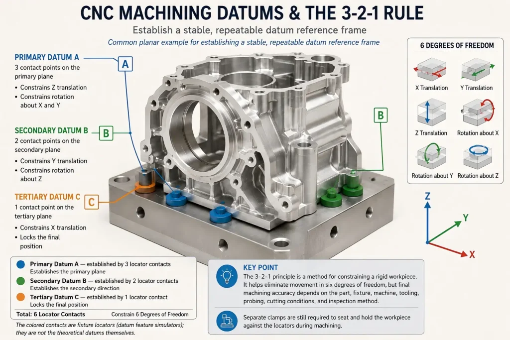
The 3-2-1 principle is a common method for constraining a rigid workpiece, but it does not automatically guarantee ±0.005 mm or any other machining tolerance. Final capability depends on the part geometry, material condition, fixture, machine, tooling, temperature, probing, machining sequence, and inspection method.
Engineer’s Note
A good primary datum should support the functional intent of the part while providing stable and repeatable contact. A large but uneven surface may introduce rocking, while a smaller qualified surface may provide a more reliable setup.
Quick Answer
The main CNC machining datum references are:
- Primary datum: Establishes the main orientation of the part.
- Secondary datum: Controls an additional direction and prevents rotation relative to the primary datum.
- Tertiary datum: Completes the part location by constraining the remaining required movement.
These references create an ordered datum reference frame.
In the workshop, the drawing datums must be connected to:
- Physical fixture contact
- Machining datums
- CNC work offsets such as G54 or G55
- Probe alignment
- Inspection alignment
- Functional assembly requirements
The best datum is not always the largest or easiest surface to clamp. It should be selected according to function, stability, repeatability, accessibility, part rigidity, and inspection requirements.
The 3-2-1 Principle: Eliminating 6 Degrees of Freedom
A rigid part in three-dimensional space can move along three linear directions and rotate around three axes. A common 3-2-1 fixture arrangement uses six contact points to constrain these six degrees of freedom.
Primary Datum: Three Contact Points
Three non-collinear contact points establish the primary plane.
In a common planar setup, this constrains:
- Translation normal to the primary plane
- Rotation around two axes lying in the primary plane
The three supports must be stable and positioned so that the workpiece does not rock or deform.
Secondary Datum: Two Contact Points
Two additional contact points establish a secondary direction.
In a common planar setup, they constrain:
- One remaining linear movement
- Rotation around the normal axis of the primary plane
The secondary contacts should not force the part away from the primary supports.
Tertiary Datum: One Contact Point
The final contact point constrains the remaining linear movement and completes the location of the part.
The 3-2-1 model explains how a fixture can locate a rigid component without unnecessary over-constraint. Flexible parts, castings, freeform surfaces, and components using datum targets may require a different practical contact and support strategy.
Small errors can still accumulate when the datum changes between setups, fixtures, and inspection alignments.
To see how small datum and setup errors accumulate across related features, review our CNC machining tolerance stack-up guide.
Datum, Datum Feature, and Datum Reference Frame
These terms are related but should not be treated as interchangeable.
| Term | Practical Meaning | Example |
|---|---|---|
| Datum | A theoretically exact point, axis, line, or plane | The exact plane established as Datum A |
| Datum feature | The physical part feature identified on the drawing | A machined mounting face marked as Datum Feature A |
| Datum feature simulator | The physical or mathematical interface used to establish the datum | Fixture pads, a gauge pin, a CMM-fitted plane, or another specified simulator |
| Datum reference frame | The ordered coordinate system created from the referenced datums | A primary-secondary-tertiary reference such as A-B-C |
| Machining reference | The physical or constructed reference used during a machining operation | A qualified face, bore, pin hole, or temporary boss |
| CNC work offset | The coordinate location stored in the machine controller | G54, G55, or another work coordinate system |
The fixture itself is not automatically the drawing datum. It must contact or simulate the relevant datum features in a way that supports the drawing intent.
Similarly, entering a G54 value does not create a reliable datum structure by itself. The work offset is only useful when it is established from a stable and correctly identified physical reference.
ASME’s Y14.5 materials explicitly distinguish datum, datum feature, datum reference frame, material-boundary conditions, and datum feature simulation.
Drawing Datums, Machining References, Inspection Alignment, and Work Offsets
| Reference Type | Main Purpose | Practical Risk |
|---|---|---|
| Drawing datum structure | Defines the functional relationship between features using the controlled drawing or model | The datum feature may be difficult to access, flexible, unfinished, or unavailable during an early operation |
| Machining reference | Locates the workpiece during a specific machining setup | A convenient reference may not reproduce the final functional datum relationship |
| Fixture locator | Provides repeatable physical contact and support | Dirt, burrs, wear, uneven contact, or excessive clamping can shift or distort the part |
| Inspection alignment | Reproduces the required datum reference frame for measurement | A convenient best-fit or edge alignment may not represent the drawing intent |
| WCS / Work Offset | Stores the CNC program origin and orientation, such as G54 or G55 | Touch-off, probe, tool, setup, or offset errors can shift every related feature |
| Functional assembly reference | Controls how the finished component fits or operates in the final assembly | It may be overlooked when machining and inspection use easier but unrelated references |
The drawing datum structure should guide manufacturing and inspection planning. Temporary machining references may still be required, but the process must explain how the part will eventually be related back to the final functional datums.
For inspection-side datum alignment and report review, see our guide to CMM inspection for CNC machined parts.
How to Select CNC Machining Datums
1. Start with the Functional Relationship
A mating face, bearing bore, locating hole, sealing surface, or rotational axis may be important to the final assembly.
However, the most important functional feature does not automatically have to become the primary datum in every machining operation. The datum sequence should follow the controlled drawing and the required degrees of freedom.
The process planner should identify which relationships must be protected and determine how they can be reproduced during machining and inspection.
2. Use Stable and Repeatable Datum Features
A useful machining reference should be:
- Rigid enough to resist clamping and probing forces
- Accessible in the required setup
- Free from burrs and contamination
- Repeatable between parts
- Suitable for the intended fixture or probe
- Available throughout the required process stage
An unfinished casting, forging, saw-cut surface, thin wall, or cosmetic edge may require an initial qualification operation before it can become a reliable reference.
3. Plan Datum Access Before Removing Material
A datum may disappear when:
- The original stock face is machined away
- A temporary boss is removed
- The outer profile is cut free
- A surface is coated
- A locating hole is enlarged
- A fixture tab is removed
Before removing the original reference, the next setup should have another qualified feature available.
Possible transfer features include:
- Reamed locator holes
- Finished bores
- Machined mounting faces
- Dowel-pin locations
- Temporary bosses
- Probed reference surfaces
4. Use Hole or Axis Datums Only When They Match the Function
A bored or reamed hole can provide a useful datum axis when it represents a bearing, locating pin, shaft, or another functional relationship.
However, a hole centerline is not automatically more reliable than every edge or plane.
The result can be affected by:
- Bore taper
- Roundness
- Burrs
- Probe strategy
- Gauge or pin clearance
- Feature size
- Datum feature simulation
- Material-boundary modifiers
On ASME drawings, RFS applies to a controlled feature of size when no material-condition modifier is specified. Datum features of size use datum material-boundary terminology such as RMB, MMB, or LMB. RFS should therefore not be used as a reason to automatically prefer hole centerlines.
5. Avoid Over-Constraining Flexible Parts
Adding more contact points or more clamping force does not always improve accuracy.
A thin or flexible part may be forced into the fixture shape during machining and then spring back after release.
Supports should stabilize the component without creating conflicting locators or excessive deformation. The drawing or inspection plan should also state whether the part is measured freely supported or in a defined restrained condition.
Datum Transfer Across Multiple CNC Setups
Complex parts often require more than one machining orientation.
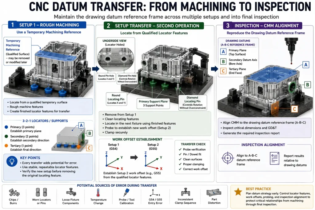
A typical process may include:
- Qualifying an initial reference surface.
- Rough machining the main geometry.
- Creating finished locator holes or bores.
- Transferring the part to a second fixture.
- Probing or locating from the qualified features.
- Finishing critical relationships.
- Inspecting the completed part from the drawing datum reference frame.
Every datum transfer creates another opportunity for error.
Possible sources include:
- Chips or burrs under the part
- Worn locating pins
- Loose fixture components
- Incorrect probe calibration
- Work-offset entry errors
- Part distortion
- Temperature change
- Inconsistent clamp sequence
- Different machining and inspection alignments
Features with important positional, angular, or coaxial relationships should be machined in the same setup where practical. When that is not possible, the transfer features and inspection plan should be defined before production.
For broader tolerance, datum, and inspection planning, review our CNC machining tolerances resource.
FAQ: CNC Machining Datums
What is the difference between a datum and a datum feature?
A datum is a theoretically exact reference, such as a plane or axis. A datum feature is the physical surface, hole, slot, width, or feature pattern on the part from which that datum is established.
What are primary, secondary, and tertiary datums?
They are an ordered set of references used to establish a datum reference frame. The primary datum provides the first orientation, the secondary datum constrains additional movement, and the tertiary datum completes the required location.
Does the 3-2-1 principle guarantee a specific machining tolerance?
No. The 3-2-1 principle explains how a rigid part can be located by constraining six degrees of freedom. Final machining accuracy still depends on the part, fixture, machine, tools, temperature, probing, machining sequence, and inspection method.
Can a hole be used as a CNC machining datum?
Yes. A hole or bore may provide a useful datum axis when it represents a functional locating, bearing, or shaft relationship and can be simulated repeatably. Bore quality, burrs, size, taper, access, and the drawing’s material-boundary requirements must still be considered.
Can an as-cast or forged surface be used as a primary datum?
It can be used when the drawing and process permit it, but variation in texture, draft, flatness, and stock condition may reduce repeatability. Tight-control parts often require qualified datum targets or an initial machining operation.
Must machining and inspection use the same physical setup?
Not necessarily. The machining fixture and CMM fixture may be different. However, the inspection alignment should reproduce the controlled drawing datum reference frame rather than using an unrelated convenient edge or best-fit alignment.
How does datum selection affect five-axis machining?
Five-axis machining still requires a valid workpiece datum and work coordinate system. The machine rotary-center calibration and tool-center-point control are machine kinematic references; they are not automatically the design datum.
A workpiece datum may be established from a face, bore, pin hole, probing feature, or another controlled reference. Angular setup error can create larger positional deviation at features located farther from the effective rotation center, so workholding, probing, calibration, and inspection must be considered together.
How should a datum be transferred between setups?
The next setup should locate from a qualified feature that remains available, such as a finished face, reamed hole, controlled bore, dowel-pin location, or temporary reference feature. The transfer should be verified before the original datum is removed.
Final Thoughts
CNC machining datums control how a component is located, machined, measured, and assembled.
A reliable datum strategy should connect:
- Functional design intent
- Datum features
- Fixture contact
- CNC work offsets
- Setup transfer
- Probe access
- Part rigidity
- Inspection alignment
The 3-2-1 principle provides a useful foundation for locating rigid components, but it should not be treated as a universal fixture design or a guarantee of a fixed machining tolerance.
For precision parts, datum planning should be reviewed together with GD&T, workholding, machining sequence, deformation risk, and inspection requirements before production.
Need Help Reviewing CNC Datums?
Send Rapid Efficient your 2D drawing, 3D model, material, quantity, tolerances, and inspection requirements.
We can review:
- Drawing datum structure
- Machining references
- Workholding and locator access
- Setup-transfer risks
- Thin-wall deformation
- Critical feature relationships
- CMM datum alignment
- Inspection-report requirements
Learn more about our precision machining services.
Rapid Efficient can coordinate drawing review, machining planning, dimensional inspection, and requested CMM reporting according to the actual project requirements.