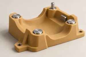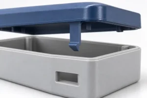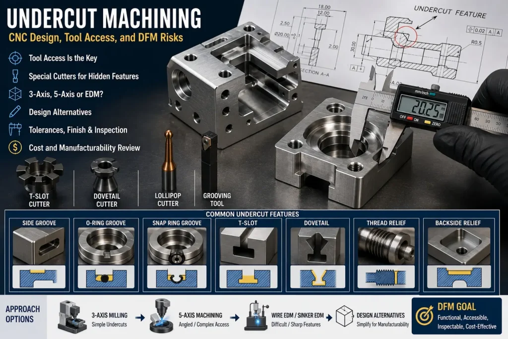
Undercut machining is not only a tooling problem.
It is a tool access problem.
A CNC part may look simple from the outside, but if a feature is hidden behind a wall, below an overhang, inside a groove, or on the reverse side of a shoulder, a standard end mill may not be able to reach it directly.
That is when undercut machining becomes important.
An undercut can affect:
- machining route
- cutter selection
- setup direction
- fixture design
- 3-axis vs 5-axis decision
- EDM review
- burr control
- surface finish
- inspection access
- machining cost
- lead time
- part redesign options
The key question is not only:
Can this undercut be machined?
A better question is:
Can this undercut be machined reliably, inspected clearly, and justified by the part function?
What Is an Undercut in CNC Machining?
In CNC machining, an undercut is a feature that cannot be reached by a standard straight cutting tool from the main machining direction.
This usually happens when material must be removed behind an edge, below a lip, inside a recessed groove, around a shoulder, or on a side surface that is blocked by nearby geometry.
Common undercut examples include:
- side grooves
- internal grooves
- O-ring grooves
- snap-ring grooves
- relief grooves
- T-slots
- dovetail features
- hidden pockets
- recessed side features
- reverse-facing shoulders
- tool clearance reliefs
- small backside cuts
- undercut thread reliefs
An undercut is not automatically bad.
Some undercuts are necessary for sealing, assembly, tool clearance, locking, or mechanical function.
The risk begins when the undercut is added without thinking about cutter access, inspection access, and cost.
Not Every Recess Is an Undercut
Many buyers use “undercut” loosely.
That can create confusion during quotation.
A recessed pocket is not always an undercut. A counterbore is not always an undercut. A slot is not always an undercut.
The difference is tool access.
| Feature Type | Is It Usually an Undercut? | Reason |
|---|---|---|
| Open pocket from top | No | A standard end mill can reach it from above |
| Straight slot on top face | No | Tool access is open |
| Counterbore | Usually no | Standard drilling or boring tools can reach it |
| Side groove behind a wall | Yes | Tool must cut sideways behind material |
| Internal O-ring groove | Often yes | Tool access may require a grooving tool or turning setup |
| Dovetail slot | Yes | Shape cannot be cut with a standard end mill |
| T-slot | Yes | Requires T-slot cutter or special tool path |
| Thread relief groove | Sometimes | Depends on part geometry and tool access |
| Backside pocket | Sometimes | May need second setup or 5-axis access |
| Hidden corner relief | Sometimes | May need lollipop cutter, EDM, or redesign |
Before deciding the process, the supplier should identify whether the feature is truly blocked from standard tool access.
For broader DFM review, see our CNC machining design guide.
Why Undercuts Increase CNC Machining Cost
Undercuts often increase cost because they interrupt the normal machining route.
A standard 3-axis milling process usually works best when tools can approach the part from simple directions.
Undercuts may require:
- special cutters
- longer tools
- smaller tools
- side milling tools
- T-slot cutters
- dovetail cutters
- lollipop cutters
- custom fixtures
- extra setups
- 5-axis positioning
- EDM
- manual deburring
- special inspection tools
The cost increase usually comes from the whole process, not only from the tool.
| Cost Driver | Why It Matters |
|---|---|
| Special cutter | May not be standard stock tooling |
| Tool rigidity | Undercut tools can be weaker or longer |
| Slow cutting | Small or special tools may need conservative cutting |
| Extra setup | Part may need to be rotated or refixtured |
| Fixture access | Workholding must leave room for the tool |
| Inspection access | Hidden features can be hard to measure |
| Burr removal | Backside burrs may be difficult to reach |
| Scrap risk | Tool breakage or poor access can damage expensive parts |
| Lead time | Tool ordering or process review may add time |
A simple undercut may be easy.
A deep, narrow, hidden, tight-tolerance undercut can become a major manufacturing risk.
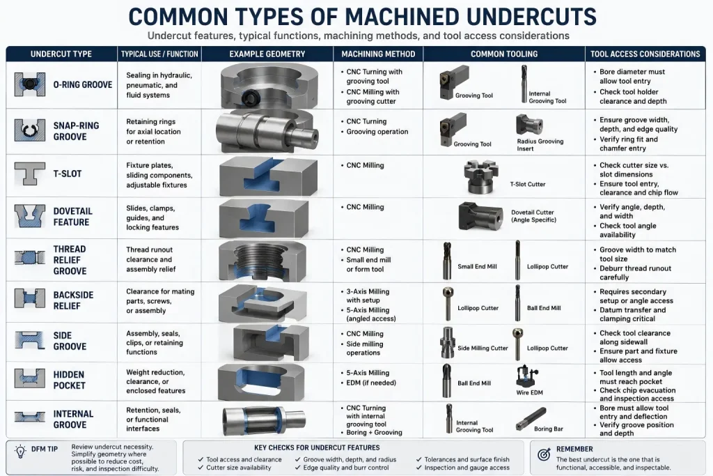
Common Types of Machined Undercuts
Different undercuts need different machining strategies.
A buyer should not assume one tool can handle all undercut geometry.
| Undercut Type | Typical Use | Machining Review |
|---|---|---|
| O-ring groove | Sealing parts, fluid systems | Groove width, depth, radius, surface finish, inspection |
| Snap-ring groove | Retaining rings, shafts, bores | Groove position, edge quality, ring fit |
| T-slot | Fixture plates, sliding blocks | T-slot cutter size, chip evacuation, corner radius |
| Dovetail | Slides, clamps, locking features | Dovetail angle, tool availability, surface finish |
| Thread relief | Thread runout, assembly clearance | Tool width, groove depth, burr control |
| Backside relief | Clearance for mating part | Setup direction, datum transfer, inspection |
| Side groove | Assembly, clip, seal, or retaining function | Tool access and cutter diameter |
| Hidden pocket | Weight reduction or clearance | 5-axis access, EDM, or design split |
| Internal groove | Bore sealing or retention | Turning, grooving, bore access |
| Undercut radius | Stress relief or assembly clearance | Cutter radius and geometry match |
A useful drawing should identify which undercut is functional.
If the undercut is only for clearance, it may be possible to simplify it.
If the undercut controls sealing, retention, or motion, it needs more careful machining and inspection planning.
Tool Access Is the First Question
The first undercut review is simple:
Can a cutter physically reach the feature?
The answer depends on:
- feature location
- nearby walls
- groove depth
- groove width
- opening size
- cutter diameter
- tool shank clearance
- tool holder clearance
- required corner radius
- part orientation
- fixture clearance
- machine axis access
A drawing may show a perfect undercut shape, but the real cutter needs room to enter, cut, retract, and avoid collision.
Tool access should be checked before confirming cost, tolerance, or lead time.
For complex multi-face access review, see our five-axis CNC machining service page.
Standard End Mills Cannot Cut Many Undercuts
A standard end mill cuts mainly from its side and bottom.
It can machine pockets, profiles, slots, holes, and many open features.
But it cannot cut material that is hidden behind a lip or underneath an overhang if the tool cannot approach that area.
This is why undercut features may need special tools.
Common undercut tools include:
| Tool Type | Typical Use | Main Limitation |
|---|---|---|
| T-slot cutter | T-slots, side grooves, retaining features | Needs enough entry space and chip clearance |
| Dovetail cutter | Angled dovetail slots and sliding features | Fixed angle limits design flexibility |
| Lollipop cutter | Backside chamfers, hidden radii, small undercuts | Tool rigidity and access are limited |
| Woodruff cutter | Keyseat-style grooves and side reliefs | Size and depth must match tool |
| Internal grooving tool | Bore grooves, O-ring grooves, retaining grooves | Bore diameter must allow tool access |
| Custom form cutter | Special profiles | Higher cost and lead time |
| EDM electrode / wire EDM | Hard-to-reach profiles in conductive materials | Not suitable for every material or geometry |
Beyond tool shape, cutter rigidity is also important in undercut milling. Tools such as T-slot cutters, Woodruff cutters, and lollipop undercutting end mills often need neck clearance behind the cutting head so the tool can reach hidden or reverse-facing surfaces.
This reduced neck area can make the tool less rigid than a standard solid end mill of similar head size. If feed rate, radial depth of cut, tool overhang, or tool engagement is too aggressive, the undercut cutter may be more sensitive to deflection, vibration, chatter, and surface marks.
For deep, narrow, or tight-tolerance undercuts, the supplier may review light multi-pass cutting, conservative finishing parameters, shorter tool reach where possible, and suitable cutter size before confirming the machining route.
The tool should be selected for the feature, not the other way around.
If a custom cutter is needed for one small detail, the buyer should ask whether that detail is truly necessary.
Undercuts in 3-Axis CNC Milling
Some undercuts can be machined on a 3-axis mill.
This usually works when:
- the undercut is shallow
- the tool has enough side access
- the part can be held securely
- the feature does not require complex angle control
- the cutter can enter and exit without collision
- inspection is possible after machining
Examples include:
- simple side grooves
- T-slots with enough entry space
- dovetail slots with standard cutter angles
- relief grooves on accessible sides
- backside chamfers reachable with lollipop cutters
- open undercut features near an edge
However, 3-axis undercut machining can become risky when the feature is deep, narrow, hidden, or close to thin walls.
A long cutter or small cutter may create:
- chatter
- tool deflection
- poor surface finish
- oversized groove width
- tool marks
- broken cutters
- burrs
- inconsistent depth
- inspection variation
For standard milling support, see our CNC milling services page.
When 5-Axis Machining Helps an Undercut
5-axis machining may help when the feature requires tool access from an angle.
It can reduce the need for multiple setups and may allow a shorter, more rigid tool to reach difficult areas.
5-axis review may be useful for:
- angled grooves
- backside features
- complex housings
- multi-face undercuts
- angled clearance reliefs
- impeller-style geometry
- organic curved parts
- aerospace-style lightweight structures
- parts where datum relationships matter across faces
But 5-axis is not automatically the answer.
A simple undercut may be cheaper with a T-slot cutter or a second setup.
A deep internal groove may be better handled by turning or EDM.
A non-functional undercut may be better removed by design change.
The process should be selected by geometry, tolerance, quantity, and function.
For process comparison, see our 5-axis vs 3-axis CNC machining guide.
When EDM Is Better Than Milling
Some undercuts are difficult or inefficient to mill.
EDM may be reviewed when the material is conductive and the feature is hard to reach with a rotating cutter.
EDM may be useful for:
- sharp internal profiles
- narrow slots
- hardened steel features
- small internal reliefs
- difficult corners
- tool steel components
- mold inserts
- deep profiles with limited tool access
However, EDM is not always better.
It may add cost, setup time, surface texture considerations, and electrode or wire access limits.
A buyer should not request EDM only because a feature looks complex.
The supplier should review whether milling, turning, EDM, 5-axis machining, or design revision gives the most practical route.
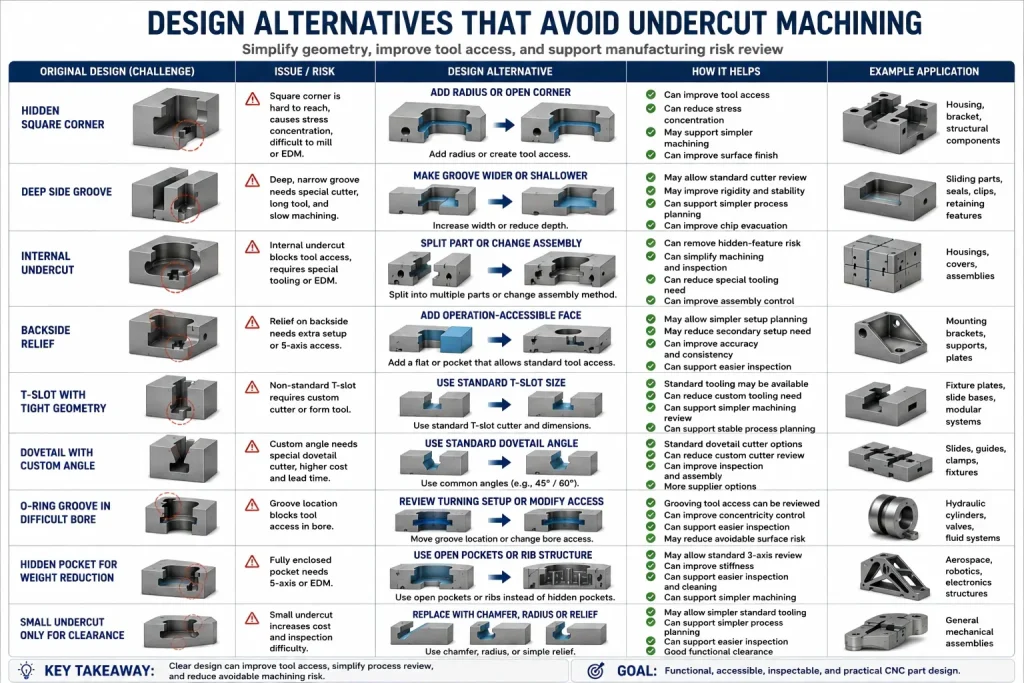
Design Alternatives That Avoid Undercut Machining
Some undercuts are functional.
Others are accidental.
If an undercut is not required for assembly, sealing, retention, or clearance, it may be better to remove it from the design.
Common design alternatives include:
| Original Design Issue | Possible Alternative |
|---|---|
| Hidden square corner | Add radius or open the corner |
| Deep side groove | Make the groove wider or shallower |
| Internal undercut | Split the part into two components |
| Backside relief | Add a second setup-accessible face |
| T-slot with tight geometry | Use a standard T-slot cutter size |
| Dovetail with custom angle | Use a standard dovetail angle |
| O-ring groove in difficult bore | Review turning setup or modify bore access |
| Hidden pocket for weight reduction | Use open pockets or ribs |
| Small undercut only for clearance | Replace with chamfer, radius, or local relief |
| Tight undercut tolerance | Define only functional surfaces tightly |
A small design change can sometimes reduce cost more than negotiating the machining price.
The best undercut is the one that is functional, accessible, and inspectable.
Undercut Tolerance Needs Extra Review
Undercut tolerance should not be copied from normal open features.
A hidden groove or backside feature may be harder to control and inspect than an open pocket.
Tolerance depends on:
- tool type
- tool rigidity
- tool wear
- setup direction
- cutter access
- groove depth
- groove width
- material
- burr control
- inspection method
- datum structure
- surface finish requirement
When spherical or lollipop cutters are used for curved undercuts, the effective cutting condition changes across the tool radius. Near the center of a spherical cutting edge, surface speed can become very low, so the tool may push or rub the material more than it cuts cleanly.
This can affect small radii, curved undercut profiles, sealing surfaces, and tight profile tolerances. For complex 3D undercuts, the supplier may review tool tilt angle, stepover, cutter contact point, finishing allowance, and inspection method before confirming the tolerance plan.
The goal is not to avoid spherical undercut tools. The goal is to avoid assuming that every point on the cutter behaves the same during finishing.
For example:
- a wide side groove may be easy to hold
- a narrow internal groove may need special tooling
- a deep T-slot may create chatter or chip issues
- a backside relief may need datum transfer
- a hidden sealing groove may need special inspection planning
The drawing should define which undercut dimensions are functional.
Do not apply tight tolerance to every surface inside the undercut unless it is truly needed.
For broader tolerance planning, see our CNC machining tolerances guide.
Surface Finish Inside Undercuts
Surface finish inside an undercut can be difficult to control.
This is especially true when the cutter is small, long, or cutting with limited chip evacuation.
Surface finish problems may include:
- tool marks
- chatter lines
- burrs
- poor corner blending
- inconsistent groove bottom
- rough sidewalls
- witness marks from multiple setups
- polishing access problems
Toolpath strategy can directly affect surface finish inside enclosed undercuts. If a cutter enters or exits directly against a functional wall, it may leave subtle witness marks, dwell marks, or local texture changes on the surface.
For critical O-ring grooves, sealing faces, or sliding undercuts, the supplier may review tangential entry and exit, lead-in and lead-out location, finishing pass direction, and whether the tool should avoid stopping on the functional surface.
Chip evacuation should also be reviewed in blind or deep internal grooves. Trapped chips can be recut during finishing and may scratch the groove wall or affect surface consistency. Air blast, coolant direction, chip clearance, and a separate finishing pass may help reduce this risk depending on material and geometry.
If the undercut is used for sealing, sliding, or assembly, surface finish should be defined clearly.
A note that only says “smooth surface” may not be enough.
Better notes may say:
- which undercut surface is functional
- whether tool marks are acceptable
- whether burrs must be removed
- whether Ra value applies inside the groove
- whether the surface must be checked after finishing
- whether the feature mates with an O-ring, retaining ring, or sliding part
For finish planning, see our CNC surface finishes guide.
Burrs Are Often Hidden in Undercuts
Undercuts can create burrs in places that are hard to see and hard to remove.
Burrs may appear at:
- groove edges
- tool exit points
- internal corners
- backside reliefs
- thread relief grooves
- T-slot edges
- O-ring groove edges
- cross-hole intersections
- retaining-ring grooves
Hidden burrs can affect:
- assembly
- sealing
- sliding motion
- ring fit
- thread fit
- inspection results
- customer acceptance
Undercut deburring should be planned before production.
If the feature is hard to reach for cutting, it may also be hard to reach for deburring.
For more edge-quality guidance, see our What Is Deburring? CNC Edge Quality, Burr Removal, and Inspection guide.
Inspection Access Can Be Harder Than Machining Access
A feature is not finished only because it was machined.
It must also be inspectable.
Undercut inspection can be difficult because the feature may be hidden, narrow, deep, or blocked by nearby geometry.
Inspection may require:
- pin gauges
- bore gauges
- depth gauges
- optical inspection
- CMM probes
- custom gauges
- sectioned first article samples
- functional fit checks
- O-ring fit checks
- retaining ring checks
Common inspection problems include:
| Undercut Feature | Inspection Challenge |
|---|---|
| Internal groove | Standard calipers cannot measure it directly |
| T-slot | Width and depth may need special gauge access |
| Dovetail | Angle and width can be hard to verify |
| Backside relief | Datum transfer may affect measurement |
| O-ring groove | Width, depth, radius, and surface finish all matter |
| Snap-ring groove | Ring fit may be more important than simple dimension |
| Hidden pocket | Visual inspection and burr check can be difficult |
| Small relief groove | Tool marks and burrs may be hard to detect |
For critical undercuts, the inspection method should be reviewed before machining.
For CMM-related planning, see our CMM inspection for CNC parts guide.
Material Changes the Undercut Strategy
The same undercut geometry may behave differently in different materials.
| Material | Undercut Machining Concern |
|---|---|
| Aluminum | Burrs, thin-wall deflection, anodizing thickness, cosmetic marks |
| Stainless steel | Tool wear, work hardening, burrs, galling, slow cutting |
| Brass | Usually clean cutting, but alloy and thread quality still matter |
| Copper | Stickiness, burrs, soft surface damage, tool marks |
| Titanium | Heat, tool wear, slow cutting, expensive scrap risk |
| Steel | Heat treatment, rust prevention, tool wear, distortion |
| POM / Delrin | Burrs, snap-fit root stress, threads, inspection force |
| PTFE | Clamping deformation, creep, soft features, measurement pressure |
| PEEK | Heat, tool wear, burrs, dimensional stability, material cost |
An undercut that is simple in aluminum may be expensive in titanium.
An internal groove that works well in brass may need extra burr control in copper.
A plastic undercut may need different edge and inspection planning from a metal undercut.
For material selection, see our CNC milling metals guide.
Drawing Notes That Help Undercut Machining
A useful drawing note can prevent quoting and production confusion.
Example 1: O-Ring Groove
O-ring groove is functional. Supplier to review groove width, depth, radius, surface finish, burr control, and inspection method before production.
This is better than only giving groove dimensions.
Example 2: T-Slot
T-slot to fit standard cutter size if possible. Supplier to review cutter access, chip evacuation, and burr removal before quotation.
This can reduce custom tooling risk.
Example 3: Dovetail Feature
Dovetail angle is functional. Supplier to review available cutter angle, tool clearance, and inspection method.
This prevents angle mismatch.
Example 4: Hidden Backside Relief
Backside relief is clearance-only. Supplier may suggest design simplification if feature increases setup or inspection risk.
This allows practical DFM feedback.
Example 5: Thread Relief
Thread relief groove is required for assembly. Supplier to review groove width, tool access, and burr control at thread runout.
This helps avoid assembly problems.
When Buyers Should Send the Part for DFM Review
Send the design for undercut review when the part has:
- side grooves
- internal grooves
- deep recesses
- hidden pockets
- O-ring grooves
- T-slots
- dovetails
- backside reliefs
- thread relief grooves
- snap-ring grooves
- tight undercut tolerance
- sealing or sliding undercut surfaces
- hard-to-reach burr-sensitive edges
- complex multi-face geometry
- expensive material
- short lead time
The review should happen before the drawing is locked.
A small change to groove width, radius, access direction, or tolerance can sometimes make the part easier to machine and inspect.
What to Send for an Undercut Machining Quote
When a part includes undercuts, the supplier needs more than a 3D model.
Send:
| Item | Why It Matters |
|---|---|
| 2D drawing | Shows tolerances, datums, critical dimensions, and notes |
| 3D model | Helps identify tool access and collision risk |
| Material grade | Affects cutter choice, burrs, tool wear, and finish |
| Quantity | Affects custom cutter and fixture decisions |
| Functional surfaces | Shows which undercut surfaces matter |
| Groove dimensions | Width, depth, radius, angle, and position |
| Mating parts | O-ring, snap ring, screw, shaft, pin, or sliding part |
| Surface finish | Important for sealing, sliding, or retention features |
| Burr requirement | Hidden burrs may affect assembly |
| Inspection requirement | Some undercuts need special gauges or CMM planning |
| Post-processing | Coating, anodizing, passivation, heat treatment, or polishing |
| Delivery target | Helps review tooling and setup time |
A good undercut RFQ does not only ask for a price.
It explains why the undercut exists and which features must be controlled.
Rapid Efficient Support for Undercut CNC Parts
Rapid Efficient can review custom CNC parts with undercuts according to geometry, tool access, material, tolerance, finish, and inspection needs.
We can review:
- side grooves
- O-ring grooves
- snap-ring grooves
- relief grooves
- T-slots
- dovetail features
- internal grooves
- backside reliefs
- hidden pockets
- undercut threads
- burr-sensitive edges
- sealing or sliding features
- 3-axis vs 5-axis access
- EDM or design revision options
- inspection method and reporting needs
If your part includes hidden grooves, backside cuts, T-slots, dovetails, O-ring grooves, or hard-to-reach reliefs, send the 2D drawing, 3D model, material, quantity, critical features, and application notes before quotation. We can review the design and suggest a suitable machining route.
Buyer Questions About Undercut Machining
What is an undercut in CNC machining?
An undercut is a feature that cannot be reached directly by a standard straight cutting tool from the main machining direction. It often requires a special cutter, extra setup, 5-axis access, EDM, or design change.
Are undercuts bad for CNC machined parts?
Undercuts are not always bad. Some are required for sealing, retaining rings, tool relief, or assembly clearance. The issue is whether the undercut can be machined, deburred, inspected, and justified by the part function.
Can a 3-axis CNC machine cut undercuts?
Some undercuts can be machined on a 3-axis CNC mill using T-slot cutters, dovetail cutters, lollipop cutters, or side-access tooling. Deeper or more hidden features may require another setup, 5-axis machining, EDM, or design revision.
Why do undercuts increase machining cost?
Undercuts can require special tools, slower cutting, extra setups, custom fixturing, harder deburring, and special inspection. The cost comes from the whole process, not only the cutter.
How can I reduce undercut machining cost?
You can reduce cost by widening grooves, using standard cutter sizes, adding access clearance, relaxing non-critical tolerances, splitting the part, replacing hidden pockets with open pockets, or confirming which undercut surfaces are truly functional.
What files should I send for undercut machining?
Send a 2D drawing, 3D model, material grade, quantity, critical dimensions, groove details, mating parts, surface finish notes, burr requirements, inspection needs, and any application condition that explains why the undercut is needed.