Deburring is the process of removing unwanted sharp edges, raised material, loose burrs, and small metal projections left after machining, drilling, milling, turning, tapping, grinding, cutting, or other manufacturing operations.
In simple terms:
Deburring makes a machined part safer, cleaner, easier to assemble, and more reliable.
But for CNC machined parts, deburring is not just a cosmetic cleanup step. Burrs can affect assembly fit, thread function, sealing surfaces, anodizing quality, coating adhesion, inspection results, packaging safety, and even whether the final part is accepted by the customer.
A good drawing should not only say “deburr.” It should define which edges matter, what edge break is acceptable, where burrs are not allowed, which surfaces are cosmetic, and whether inspection or special cleaning is required.
Fast Answer for Buyers
| Question | Better Answer |
|---|---|
| What is deburring? | Removing burrs, sharp edges, and unwanted raised material from machined parts. |
| Is deburring the same as edge breaking? | Not exactly. Deburring removes unwanted material; edge breaking intentionally softens or rounds an edge. |
| Why do CNC parts need deburring? | Burrs can affect assembly, safety, threads, sealing, finishing, inspection, and handling. |
| Are all burrs unacceptable? | No. Some minor edge conditions may be acceptable depending on the drawing and application. |
| Which edges need tighter control? | Mating faces, sealing surfaces, threads, holes, cosmetic surfaces, sliding features, and user-contact edges. |
| Should the drawing only say “deburr all edges”? | Usually not. Critical edges should be defined more clearly. |
The practical rule is simple:
Deburring should match the function of the edge. A hidden clearance edge, a sealing face, a threaded hole, and a cosmetic front surface should not all be treated with the same vague requirement.
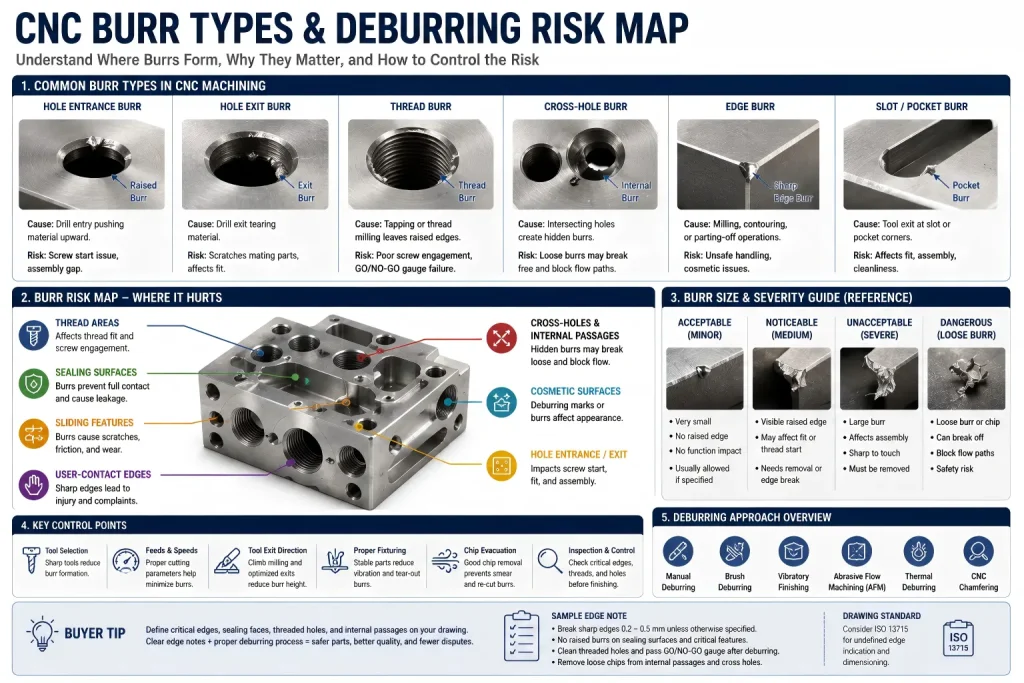
What Is a Burr?
A burr is unwanted material that remains attached to an edge, hole, slot, thread, or surface after manufacturing.
Burrs may appear as:
- sharp raised edges
- thin metal flakes
- rolled-over material
- hanging chips
- feather edges
- sharp corners
- rough breakouts
- thread burrs
- hole exit burrs
- cross-hole burrs
- loose particles inside pockets or passages
Burrs are common in CNC machining because cutting tools push, shear, tear, or deform material as they exit the workpiece.
Burrs are not always large. Some are small enough to be missed visually but still large enough to affect assembly, cleaning, coating, or inspection.
Why Burrs Form During CNC Machining
Burr formation depends on part geometry, material behavior, cutting conditions, tool wear, and machining sequence.
Common causes include:
- tool exit direction
- drilling breakthrough
- milling exit edges
- worn cutting tools
- improper feeds and speeds
- ductile material deformation
- thin walls or unsupported edges
- intersecting holes
- thread cutting
- poor chip evacuation
- aggressive cutting parameters
- material smearing instead of clean shearing
Different materials produce different burr behavior.
Aluminum may form soft rolled burrs. Stainless steel may create tough, sharp burrs. Copper can smear and drag material. Brass may machine cleanly, but burr risk still depends on alloy and edge geometry. Plastics may leave fuzz, stringing, or deformed edges.
This is why deburring cannot be selected only by part size. The method must match the material, geometry, finish requirement, and function of the edge.
Burr Risk Map for CNC Buyers
| Burr Location | Why It Matters | Buyer Risk |
| Hole entrance | Affects screw starting and assembly | Screw may not seat correctly. |
| Hole exit | Can scratch mating parts or block fit | Part may fail assembly. |
| Threaded holes | Affects thread gauge and screw fit | GO/NO-GO gauge may fail. |
| Cross holes | Burrs may hide inside intersecting passages | Loose burrs may break free later. |
| Sealing surfaces | Burrs can prevent full contact | Leakage or uneven compression may occur. |
| Sliding faces | Burrs can scratch or jam moving parts | Wear and functional failure risk increases. |
| Cosmetic edges | Burr removal marks may be visible | Appearance rejection risk increases. |
| User-contact edges | Sharp edges can cause injury | Safety and handling complaints may occur. |
| Thin walls | Deburring can distort or over-round edges | Dimension and appearance may be affected. |
| Internal pockets | Chips and burrs may remain trapped | Cleaning and contamination problems may occur. |
The hardest burrs to manage are often not the visible ones. Hidden burrs inside cross holes, threads, slots, grooves, and deep pockets can create the biggest downstream problems.
Deburring vs Edge Breaking vs Chamfering
These terms are related, but they are not the same.
| Term | Meaning | Practical Use |
| Deburring | Removing unwanted burrs or raised material | General cleanup after machining. |
| Edge breaking | Lightly softening a sharp edge | Safer handling and lower burr risk. |
| Chamfering | Cutting a defined angled edge | Assembly lead-in, screw entry, cosmetic edge, or drawing-defined edge. |
| Radiusing | Creating a rounded edge | Better stress distribution, handling, coating, or appearance. |
| Polishing | Smoothing a visible surface | Cosmetic or friction-related applications. |
A drawing note such as:
Deburr all edges
does not always tell the supplier whether the buyer wants a light edge break, a defined chamfer, a smooth radius, or only removal of loose burrs.
For critical parts, the drawing should define the edge condition more clearly.
Examples:
Break sharp edges 0.2–0.5 mm.
No raised burrs on sealing face.
Chamfer threaded hole entry 90° × 0.5 mm.
Radius user-contact edges R0.5 minimum.
The right note depends on function.
For higher-precision drawings, qualitative notes such as “deburr all edges” may not be enough. International drawings may use ISO 13715-style edge indications to define edges of undefined shape more clearly.
This matters because different edge notes can mean very different things:
- a small burr may be allowed within a defined limit
- a sharp edge may need to be removed
- an intentional edge break may be required
- a chamfer or radius may need to be dimensioned separately
- an edge may need to remain functionally sharp
For example, a drawing may define a maximum permitted burr or a required material removal range instead of using a vague text note. This helps the buyer and supplier agree on whether the edge should be left nearly sharp, lightly broken, chamfered, radiused, or fully burr-free.
For standard commercial CNC parts, a simple edge note may be acceptable. For sealing faces, sliding features, user-contact edges, cosmetic surfaces, or inspected components, a defined edge condition is safer than a general “deburr” instruction.
Common Deburring Methods for CNC Parts
There is no single best deburring method for all parts. Each method has strengths and risks.
| Deburring Method | Best For | Main Risk |
| Manual deburring | Prototypes, low-volume parts, selective edges | Operator variation and inconsistent edge size. |
| Hand scraping | Precision edges, small burrs, local cleanup | Can leave marks if not controlled. |
| Abrasive paper or pads | Cosmetic edge smoothing | May change appearance or round too much. |
| Rotary tools | Local burr removal, holes, slots | Can overcut edges or leave swirl marks. |
| Brush deburring | General edge cleanup and small burrs | May not remove heavy burrs or hidden burrs. |
| Tumbling or vibratory finishing | Batch parts and general edge smoothing | May affect dimensions, edges, and cosmetic faces. |
| Thermal deburring | Internal burrs in some metal parts | Requires process review and material suitability. |
| Electrochemical deburring | Targeted burr removal in hard-to-reach areas | Requires special setup and control. |
| Abrasive flow machining | Internal passages, cross holes, and inaccessible burrs | Requires route review, cleaning control, and cost evaluation. |
| Robotic deburring | Repeatable production edges | Setup cost and fixture control matter. |
| Machined chamfering | Drawing-defined edges | Adds machining time but improves control. |
For custom CNC parts, the best deburring process is usually selected after reviewing the drawing, material, edge function, cosmetic requirements, and quantity.
Manual Deburring: Useful but Not Always Repeatable
Manual deburring is common in prototype and low-volume CNC machining because it is flexible and can target specific edges.
It may use:
- files
- scrapers
- knives
- abrasive stones
- abrasive pads
- rotary tools
- countersinks
- small brushes
- polishing tools
Manual deburring is not bad by default. Skilled manual deburring can be very effective for complex parts.
The risk is repeatability. If the drawing does not define the edge condition, different operators may remove different amounts of material. One part may have a clean light break, while another may have visible tool marks or an oversized edge radius.
Manual deburring should be controlled carefully when the part has:
- cosmetic surfaces
- thin walls
- sealing faces
- small threads
- sharp functional corners
- tight dimensions near edges
- visible front panels
- user-contact edges
For critical cosmetic parts, the RFQ should specify which faces must be protected and whether deburring marks are acceptable.
Mechanical and Batch Deburring
Batch deburring methods such as tumbling, vibratory finishing, abrasive flow, or brush finishing can be useful when many parts need consistent edge smoothing.
These methods can reduce hand labor and improve consistency, but they are not suitable for every part.
Potential risks include:
- rounding edges too much
- changing critical dimensions
- dulling sharp functional corners
- damaging thin features
- creating surface texture changes
- trapping media inside holes
- affecting threads or small bores
- scratching cosmetic faces
- mixing parts and causing contact marks
Batch deburring works best when the part is designed for it. Thin ribs, fragile edges, deep blind holes, precision slots, and threaded features should be reviewed before choosing this route.
If a part has critical dimensions, the buyer should define whether batch finishing is acceptable.
Internal cross-holes and fluid passages need special attention. In manifolds, hydraulic blocks, pneumatic components, cooling plates, and clean gas or fluid pathways, the most dangerous burr may be hidden inside the part.
Manual tools may not reach intersecting internal holes reliably, and normal tumbling media may not remove burrs deep inside complex passages. If a loose burr breaks free later, it can block a flow path, damage a downstream component, or create contamination risk.
For these cases, the deburring route should be reviewed before quotation. Abrasive Flow Machining, also called AFM or extrude honing, may be considered for some internal passages. In this process, an abrasive-laden medium is forced through the internal channels to smooth edges and reduce burrs in areas that are difficult to reach by hand tools.
AFM is not required for every part, and it should be reviewed against tolerance, surface finish, cleanliness, cost, and cleaning requirements. But when a CNC part has sealed internal passages, intersecting holes, or fluid-contact features, the RFQ should not simply say “deburr.” It should define how internal burr risk will be controlled.
Deburring for Holes and Threads
Holes and threads are among the most common areas where burr problems appear.
Burrs may form at:
- drilled hole entrances
- drilled hole exits
- counterbore transitions
- countersinks
- thread starts
- blind hole bottoms
- tapped holes
- cross-hole intersections
- milled slots breaking into holes
Thread burrs can prevent screws from starting correctly, damage mating hardware, or cause GO/NO-GO gauge failure.
For threaded holes, a drawing should define whether the thread must be cleaned, protected, or inspected after deburring.
Example notes:
Deburr threaded holes. Threads must pass GO/NO-GO gauge after finishing.
Remove loose chips from blind holes before packing.
Chamfer thread entry 90° × 0.5 mm.
No raised burrs around threaded holes on mating surface.
For high-requirement threaded holes, the sequence of deburring also matters. A common risk is trying to clean or chamfer the thread entrance after tapping with an unguided hand tool. If the tool is tilted or pushed unevenly, it can cut into the first thread, damage the thread start, or create an uneven lead-in.
This may not be obvious visually, but it can affect screw starting, thread gauge engagement, or the seating of a mating component.
When the thread entrance is function-critical, it is usually safer to machine the entrance chamfer or countersink on the CNC spindle before tapping or thread milling. This keeps the chamfer concentric with the hole, gives the tap or thread mill a cleaner lead-in, and reduces the chance of hand-deburring damage at the first thread.
Manual cleanup may still be acceptable for general parts, but precision threaded holes should define the entry chamfer, thread inspection, and acceptable burr condition before production.
For deeper thread design issues, see tapped hole vs threaded hole.
Deburring Before Surface Finishing
Deburring affects surface finishing. A burr that remains before anodizing, plating, passivation, painting, bead blasting, polishing, or coating may become more visible after finishing.
For example:
- anodizing can highlight machining marks and burr-removal scratches
- plating can build up around edges
- passivation does not remove heavy burrs
- bead blasting can soften minor marks but may not fix raised burrs
- painting may reveal edge defects after curing
- polishing can round edges or change flatness if uncontrolled
If a part will be anodized, burrs and sharp edges should be reviewed before finishing. Sharp edges can increase coating inconsistency, edge chipping, or burn risk in hard anodizing.
For more detail, see aluminum anodizing defects and the CNC surface finishes guide.
Deburring and Dimensional Risk
Deburring removes material. That sounds simple, but it matters when the edge is close to a critical dimension.
Deburring can affect:
- slot width
- hole entry diameter
- sealing face flatness
- small chamfers
- cosmetic edge width
- thin wall thickness
- press-fit edges
- bearing seats
- locating surfaces
- assembly contact points
If a drawing gives a tight dimension but only says “deburr all edges,” the supplier may not know how much edge removal is allowed.
For example, a heavy edge break on a small precision slot may reduce the functional contact area. A large chamfer near a sealing face may reduce sealing width. Aggressive deburring near a press-fit feature may affect assembly.
For tight tolerance parts, edge condition should be included in the tolerance and inspection plan.
For broader tolerance planning, see the CNC machining tolerances guide.
Cosmetic Deburring vs Functional Deburring
Not all deburring goals are the same.
A cosmetic part needs the visible surface to look clean. A functional part needs the edge to assemble, seal, slide, or protect the user. Sometimes these goals conflict.
| Requirement Type | Deburring Priority | Risk If Unclear |
| Cosmetic surface | Clean appearance, no visible marks | Deburring scratches may cause rejection. |
| Sealing face | No raised burrs, flat contact | Leakage or uneven sealing. |
| Sliding feature | Smooth edge without loose burrs | Wear, scratching, or jamming. |
| Threaded hole | Clean thread start and gauge fit | Screw assembly failure. |
| User-contact edge | Safe handling | Injury or complaint. |
| Precision slot | Edge control without over-rounding | Fit or location issue. |
| Hidden internal passage | Remove loose burrs and chips | Contamination or later failure. |
The buyer should identify which surfaces are cosmetic and which edges are functional before production.
A hidden edge can usually accept a different deburring standard than a visible customer-facing edge.
Drawing Notes That Prevent Deburring Disputes
A vague note can create different expectations between buyer and supplier.
| Buyer Intention | Better Drawing or RFQ Note |
| General burr removal | Remove loose burrs and sharp edges. |
| Light edge break | Break sharp edges 0.2–0.5 mm unless otherwise specified. |
| No visible burrs | No raised burrs allowed on visible A surfaces. |
| Sealing surface protected | No raised burrs or deburring scratches on sealing face. |
| Threaded holes controlled | Threads must be clean and pass GO/NO-GO gauge after deburring. |
| Cosmetic surface protected | Deburring marks not allowed on cosmetic faces. |
| Internal chips removed | Clean blind holes, cross holes, and pockets before packing. |
| Internal passage burr control | Internal cross-hole burr removal method to be reviewed before production. |
| Surface finish after deburring | Deburr before anodizing, plating, passivation, or painting. |
| Batch finishing restricted | Tumbling or vibratory finishing requires approval. |
| Critical edge radius | Radius R0.5 required on user-contact edges. |
| ISO 13715-style edge control | Define permitted burr or required edge break on inspected edges. |
If edge condition matters, do not rely only on:
Deburr all edges.
That note is useful for general cleanup, but it may be too vague for critical surfaces.
For broader part design planning, review the CNC machining design guide before locking critical edge conditions, wall thickness, holes, threads, and assembly faces.
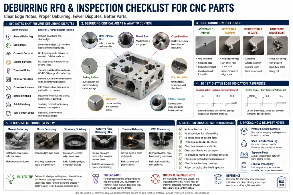
Inspection Checklist for Deburred CNC Parts
Deburring inspection should match the part function.
Common inspection points include:
- no loose burrs
- no sharp handling edges
- no raised burrs on mating faces
- thread gauge fit
- clean hole entrances and exits
- clean cross holes
- no trapped chips in pockets
- cosmetic faces protected
- edge break within drawing requirement
- no over-rounding of critical edges
- no deburring scratches on visible faces
- no media trapped after batch finishing
- no burrs before coating or anodizing
- clean packaging after final inspection
For many parts, visual inspection is enough. For functional edges, thread gauges, mating hardware checks, CMM checks, or specific edge measurement may be required.
The inspection method should be defined before production when the edge affects fit, function, or customer acceptance.
Material Effects on Burr Formation
Different materials create different burr risks.
| Material | Burr Behavior | Deburring Comment |
| Aluminum | Soft rolled burrs and sharp edge burrs are common | Easy to deburr, but cosmetic scratches can appear. |
| Stainless steel | Tough, sharp burrs and work-hardened edges | Requires controlled tools and edge review. |
| Brass | Often machines cleanly depending on alloy | Burrs still occur at holes, slots, and thin edges. |
| Copper | Can smear, drag, and form gummy burrs | Needs careful tooling and cleaning. |
| Titanium | Strong burrs and heat-related edge issues | Process control matters. |
| Plastics | Fuzz, stringing, or deformed edges | Cutting sharpness and heat control matter. |
The same deburring method will not behave the same way on aluminum, stainless steel, copper, and plastic.
For stainless steel parts, edge burrs may be harder to remove and may affect handling, passivation, or assembly. For more material-specific context, see the stainless steel CNC machining guide.
When Deburring Should Be Reviewed Before Quotation
Deburring should be reviewed early when the part has:
- tight tolerances near edges
- visible cosmetic surfaces
- sealing faces
- medical or clean equipment requirements
- food equipment requirements
- internal channels
- cross holes
- threaded holes
- very small holes
- thin walls
- sharp functional edges
- anodizing, plating, passivation, or painting after machining
- high-volume production
- parts that must be safe to handle
In these cases, deburring may affect cost, lead time, inspection method, and finishing route.
If the part is simple, deburring may be included as a standard machining cleanup step. If the part has critical edges, it should be treated as a defined manufacturing requirement.
Buyer Questions Before Quotation
Is deburring required for all CNC parts?
Most CNC parts need some level of deburring, but the amount depends on the drawing, material, edge function, and finish requirement. Some edges only need light cleanup, while others need a controlled chamfer, radius, or inspection requirement.
Is deburring the same as chamfering?
No. Deburring removes unwanted burrs. Chamfering creates a defined angled edge. A chamfer may also help remove burrs, but it is a controlled geometry, not just cleanup.
Can deburring affect tolerances?
Yes. Deburring removes material near edges. If the edge is part of a slot, seal, thread, press fit, or cosmetic surface, the amount of edge removal should be controlled.
Can anodizing hide burrs?
No. Anodizing usually does not hide burrs or tool marks. It can make surface preparation problems more visible. Burrs should be reviewed before anodizing.
How should I write deburring on a drawing?
For general parts, “Remove burrs and break sharp edges” may be enough. For critical parts, define edge break size, protected surfaces, thread inspection, sealing faces, cosmetic requirements, and internal passage requirements.
Do threaded holes need special deburring?
Often yes. Threaded holes should be cleaned and inspected if they affect assembly. For important threads, define GO/NO-GO gauge inspection, entry chamfer, or mating screw checks.
When should AFM deburring be considered?
AFM may be considered when a part has internal cross-holes, sealed flow paths, hydraulic passages, pneumatic channels, cooling passages, or clean fluid pathways where burrs cannot be reliably reached by normal hand tools or batch finishing.
Is ISO 13715 always required for deburring?
No. Many commercial CNC parts can use simpler edge notes. ISO 13715-style edge indication is more useful when the edge condition must be inspected, documented, or controlled more precisely.
How Rapid Efficient Reviews Deburring Requirements
Rapid Efficient supports custom CNC machining projects with deburring, edge breaking, chamfering, surface finishing, and inspection requirements. Before quotation, we can review burr risk, edge function, cosmetic surfaces, threads, holes, sealing faces, internal passage burr risk, tolerance impact, finishing route, inspection needs, packaging, and delivery schedule.
For deburring-sensitive CNC parts, we recommend sending:
- 2D drawing
- 3D CAD file
- material grade
- edge break or chamfer requirements
- cosmetic surface requirements
- thread and hole requirements
- internal passage or cross-hole requirements
- sealing or mating surface requirements
- surface finishing requirement
- inspection method if required
- annual or batch quantity
If your drawing only says “deburr all edges,” send the file before production so the actual edge requirement can be reviewed clearly.
Material certificates, CMM reports, and inspection reports are available depending on project requirements. For suitable rapid delivery projects, lead times may be as fast as 3–7 working days after drawing review and production confirmation.
If you are not sure whether your part needs simple deburring, controlled edge breaking, chamfering, tumbling, brushing, AFM deburring, or special inspection, send your drawing to Rapid Efficient for deburring and RFQ review before production.