Aluminum anodizing defects are not always caused by the anodizing tank. Many problems begin earlier, during material selection, CNC machining, deburring, cleaning, handling, masking, or unclear RFQ requirements.
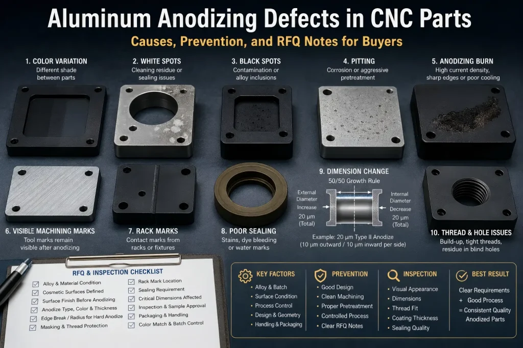
For CNC machined aluminum parts, the most common anodizing defects include color variation, white spots, black stains, pitting, burning, cloudy surfaces, poor sealing, visible machining marks, rack marks, and uneven finish between batches.
The practical answer is this:
Anodizing makes the aluminum surface more controlled, but it also makes many hidden problems more visible. If the raw material, machining marks, burrs, surface contamination, alloy choice, or drawing notes are not controlled before finishing, anodizing can expose those problems instead of hiding them.
For buyers, the goal is not only to ask for “black anodizing” or “clear anodizing.” The better goal is to define the alloy, surface finish, cosmetic faces, masking areas, color expectation, sealing requirement, inspection boundary, and packaging requirement before production.
Fast Defect Map for Buyers
| Defect Seen After Anodizing | Common Cause | Buyer Action |
|---|---|---|
| Color mismatch | Different alloy, batch, surface texture, coating thickness, or dye absorption | Keep critical cosmetic parts in the same material batch and define color tolerance. |
| White spots or cloudy areas | Cleaning residue, etching variation, poor rinsing, sealing issue, or local contamination | Review pretreatment, surface condition, and sealing requirement. |
| Black spots or dark stains | Alloy inclusions, embedded contamination, poor cleaning, or local corrosion | Confirm material grade, handling, and cleaning before finishing. |
| Pitting | Base material defects, corrosion before anodizing, aggressive pretreatment, or contamination | Inspect raw material and machined surfaces before anodizing. |
| Burning | High local current density, poor contact, sharp edges, thin features, or poor bath movement | Review part geometry, rack contact, edge condition, and anodizing process risk. |
| Visible machining lines | Tool marks, inconsistent polishing, or uneven bead blasting before anodizing | Define pre-anodize surface finish and cosmetic faces. |
| Rack marks | Contact points required for electrical connection | Define acceptable rack areas before finishing. |
| Poor sealing | Incorrect sealing process, contamination, or insufficient sealing control | Specify sealing requirement when corrosion or dye stability matters. |
| Uneven finish after assembly | Mixed lots, different machining directions, or different finish routes | Control batch, finish direction, and part grouping. |
The most important point is simple: anodizing quality is a system result, not only a finishing result.
Why Anodizing Defects Happen
Anodizing is an electrochemical process. The aluminum part becomes part of an electrical circuit, and an oxide layer grows on the aluminum surface under controlled conditions.
That means the final result depends on many linked factors:
- aluminum alloy
- raw material batch
- heat treatment
- CNC machining marks
- sharp edges and burrs
- surface roughness
- cleaning and degreasing
- etching and desmutting
- rack contact
- current density
- bath temperature
- agitation and electrolyte flow
- dye absorption if colored
- sealing quality
- packaging and storage
If one step is unstable, the final anodized surface may show defects.
This is why two parts can both be “6061 aluminum, black anodized” but still look different after finishing.
Defect 1: Color Variation Between Parts
Color variation is one of the most common complaints in anodized aluminum CNC parts.
It may appear as:
- one part darker than another
- one batch slightly blue, gray, brown, or purple
- uneven color on the same part
- different shade between machined faces and bead blasted faces
- mismatch between replacement parts and previous production batches
Color variation can be caused by:
- different aluminum alloy grades
- different material batches
- different heat treatment conditions
- different surface roughness
- uneven polishing or bead blasting
- inconsistent oxide thickness
- dye concentration or time variation
- sealing differences
- part geometry and drainage differences
For CNC parts, the machining stage matters because tool marks, cutter direction, and surface roughness can affect how the anodized finish reflects light.
A buyer should not assume that “black anodized” means every part will be visually identical. If color matters, the RFQ should define acceptable range, cosmetic faces, batch control, and whether a sample approval is required.
Defect 2: White Spots, Cloudy Areas, or Water Marks
White spots and cloudy anodized areas may come from cleaning, rinsing, sealing, or surface contamination.
Common causes include:
- incomplete degreasing
- alkaline cleaning residue
- trapped liquid in blind holes or pockets
- water marks after rinsing
- poor drying before packing
- sealing residue
- local surface contamination
- fingerprints or handling marks before anodizing
Parts with blind holes, deep pockets, counterbores, internal channels, or threaded holes are more likely to trap liquid. If liquid remains in a pocket during pretreatment, anodizing, dyeing, sealing, or drying, the surface may show stains or cloudy marks.
Design and packaging matter here. A part that looks easy to machine may be difficult to clean and dry after anodizing.
For RFQs, buyers should identify:
- blind holes
- deep pockets
- internal channels
- cosmetic faces
- areas where water marks are not acceptable
- cleaning or sealing requirements
- packaging needs after finishing
Defect 3: Black Spots and Dark Stains
Black spots are often blamed on the anodizing process, but the root cause may be earlier.
Possible causes include:
- alloy inclusions
- embedded iron or steel contamination
- tool or fixture contamination
- poor cleaning before anodizing
- corrosion before finishing
- local chemical attack
- smut not fully removed during pretreatment
- residue inside threads or pockets
Black marks are especially risky on clear anodized or light-colored parts because defects are easier to see.
For CNC machined parts, contamination can happen during:
- raw stock handling
- machining
- deburring
- tumbling
- steel brushing
- contact with carbon steel tools or tables
- storage before finishing
If cosmetic appearance is critical, the supplier should protect the machined surface before anodizing and avoid handling methods that can embed foreign material into the aluminum surface.
Defect 4: Pitting After Anodizing
Pitting appears as small holes, dots, or localized surface attacks.
It may be caused by:
- poor raw material surface quality
- corrosion before anodizing
- aggressive chemical pretreatment
- local contamination
- inclusions in the aluminum alloy
- trapped chemicals
- chloride contamination
- poor rinsing between process steps
Pitting is not always created during anodizing. Sometimes anodizing simply makes existing material or surface defects easier to see.
Pitting risk increases when parts have:
- rough machined surfaces
- sharp internal corners
- uncleaned pockets
- poor storage before finishing
- fingerprints or oil residue
- long waiting time between machining and anodizing
- mixed alloy or unknown stock
For critical cosmetic parts, inspect the machined surface before anodizing. Once anodizing exposes pitting, repair may require stripping, re-machining, polishing, or remaking the part.
Defect 5: Anodizing Burn
Anodizing burn is a more serious defect. It may appear as dark, rough, powdery, gray, or locally damaged areas.
Common risk factors include:
- excessive local current density
- poor electrical contact
- insufficient electrolyte movement
- poor cooling
- sharp edges
- thin fins
- deep pockets
- heavy coating requirement
- hard anodizing on complex geometry
- poor rack design
Burning often appears near corners, edges, contact areas, thin sections, or areas where current distribution is uneven.
Sharp geometry can make this problem worse. During anodizing, current tends to concentrate around sharp edges, corners, points, thin ribs, and high-aspect-ratio features. If local current density rises faster than the bath can control heat and oxide growth, the fresh anodic layer may break down locally and leave a rough, powdery, or chalky burned area.
For hard anodizing or thicker coating requirements, edge design should be reviewed before production. A useful DFM rule is to avoid razor-sharp 90° edges on anodized aluminum parts. When the design allows it, specify a small edge break or corner radius, often around 0.3 mm to 0.5 mm for critical anodized edges.
This does not guarantee that burn can never occur, but it helps reduce current crowding, improves coating continuity around edges, and lowers the risk of edge chipping after assembly or handling.
For CNC parts, design matters. Very sharp edges, thin walls, deep slots, or complex cooling fins may increase anodizing risk. Deburring and edge break requirements should be reviewed before finishing.
A simple note such as:
Hard anodize black
may not be enough for complex parts. If the part has thin fins, sealing grooves, sharp edges, or critical cosmetic areas, the drawing should define cosmetic faces, rack areas, edge requirements, and coating thickness expectations.
Defect 6: Visible Machining Marks After Anodizing
Anodizing does not hide tool marks. In many cases, it makes them more visible.
Visible machining marks can come from:
- inconsistent cutter paths
- different tool wear between parts
- vibration marks
- re-cut marks
- uneven polishing
- inconsistent bead blasting
- mixed finish directions
- burr removal marks
- hand sanding variation
This matters for covers, bezels, enclosures, knobs, brackets, and other visible aluminum parts.
If the buyer expects a uniform cosmetic surface, the RFQ should not only say:
Anodized black
It should define the surface condition before anodizing:
Bead blast before black anodizing. Cosmetic A surfaces must be uniform. Tool marks not acceptable on visible faces.
Or:
Machined finish acceptable. Tool marks allowed on non-cosmetic faces.
Without this boundary, the supplier may quote a normal machined anodized finish while the buyer expects a cosmetic product finish.
For surface condition planning, see the CNC surface finishes guide.
Defect 7: Rack Marks and Contact Marks
Anodizing requires electrical contact. That means the part must be held by racks, clamps, wires, or contact points during processing.
Rack marks are not always defects. They are often a necessary result of the anodizing process.
The real problem is when rack marks appear on:
- visible faces
- sealing faces
- assembly surfaces
- precision locating surfaces
- cosmetic edges
- customer-facing surfaces
To avoid disputes, the drawing or RFQ should define acceptable rack locations before production.
Better notes include:
| Requirement | Better RFQ Note |
| Rack marks not allowed on visible faces | Rack contact allowed only on non-cosmetic surfaces. |
| Sealing face must remain clean | No rack marks, stains, or raised defects on sealing face. |
| Contact area acceptable | Rack mark acceptable in hidden mounting area. |
| Critical cosmetic part | Supplier to confirm rack position before anodizing. |
If no rack location is specified, the anodizer must choose a practical contact point. That contact point may not match the buyer’s cosmetic expectation.
Defect 8: Poor Sealing or Dye Bleeding
After anodizing, sealing is often used to close or stabilize the porous oxide structure. Poor sealing can affect corrosion resistance, staining resistance, and dye stability.
Problems may include:
- dye bleeding
- color fading
- water marks
- white residue
- poor corrosion performance
- surface staining after handling
- inconsistent appearance after cleaning
Sealing performance can depend on sealing chemistry, time, temperature, water quality, contamination, and part geometry.
For colored anodized parts, sealing is especially important because poor sealing can affect long-term color stability.
If corrosion resistance, outdoor use, cleaning resistance, or color stability matters, the RFQ should clearly state the sealing requirement and inspection expectation.
Defect 9: Dimension Changes After Anodizing
Anodizing builds an oxide layer on the aluminum surface. Part of the oxide grows inward and part grows outward from the original surface.
As a practical shop-floor rule of thumb, anodized coating growth is often estimated using a 50/50 build-up and penetration model. Approximately half of the total coating thickness penetrates into the aluminum base metal, while the other half builds outward from the original surface.
For example, if a Type II anodized coating is specified at 20 μm total thickness, the outward build-up may be estimated at about 10 μm per surface. An external diameter may therefore increase by about 20 μm total, while an internal bore may become about 20 μm smaller in diameter.
For thicker Type III hard anodizing, the effect becomes more important. A 50 μm total coating may create about 25 μm of outward build-up per surface. If a bearing bore, press-fit diameter, sealing groove, thread, or sliding feature is not compensated before anodizing, the finished part may pass machining inspection but fail assembly after finishing.
This is why tight tolerance aluminum parts should not treat anodizing as a cosmetic-only process. Critical dimensions, coating thickness, masking, and post-anodize inspection should be reviewed together before machining.
Anodizing can affect:
- hole diameter
- slot width
- thread fit
- bearing fits
- press fits
- sealing grooves
- mating surfaces
- tight tolerance dimensions
For many general parts, the change may be acceptable. For precision parts, it must be planned.
Critical features may need:
- masking
- post-anodize machining
- tolerance compensation
- different coating thickness
- thread protection
- functional gauge inspection after anodizing
A buyer should not apply a tight tolerance and a thick anodized coating without considering how the finish affects the final dimension.
For tolerance planning, see the CNC machining tolerances guide.
Defect 10: Thread and Hole Problems After Anodizing
Threaded holes, blind holes, and small bores can create problems after anodizing.
Common issues include:
- tight threads
- poor screw fit
- trapped chemicals
- poor cleaning inside holes
- white residue in blind holes
- dye or sealing residue
- damaged threads after masking removal
- coating buildup affecting assembly
If the thread must remain functional after anodizing, the drawing should define whether the thread is:
- anodized
- masked
- chased after anodizing
- inspected after anodizing
- protected during finishing
For important threaded holes, an RFQ note may say:
Mask threaded holes before anodizing.
or:
Threaded holes must pass GO/NO-GO gauge after anodizing.
If the hole is cosmetic only, the requirement may be different. The key is to state it before production.
For thread-specific design issues, see tapped hole vs threaded hole.
How Alloy Choice Affects Anodizing Defects
Not all aluminum alloys anodize the same way.
| Aluminum Alloy | Anodizing Behavior | Practical Comment |
| 6061 | Usually good for general anodizing | Common choice for CNC parts and colored anodizing. |
| 6063 | Often good cosmetic anodizing | Common in extrusions and visible aluminum parts. |
| 6082 | Generally workable | May vary by batch and finish requirement. |
| 7075 | Can be more difficult for uniform cosmetic color | Often used for strength, but color consistency may need review. |
| 2024 | More difficult because of copper content | Corrosion and cosmetic requirements should be reviewed carefully. |
| Cast aluminum | Often more difficult | Porosity and silicon content may affect appearance. |
This is why machinability and anodizing appearance should not be treated as the same requirement. High-strength aluminum alloys such as 7075 and 2024 can machine well for structural parts, but their alloying elements make cosmetic anodizing more difficult to control.
7075 contains higher zinc and copper content, while 2024 contains higher copper content. These alloying elements and local material variations can react differently during cleaning, etching, desmutting, anodizing, dyeing, and sealing. The result may be darker gray tone, cloudy areas, uneven dye absorption, or more visible batch-to-batch color variation.
For high-visibility housings, covers, bezels, knobs, and multi-part assemblies that must match visually, 6000-series aluminum such as 6061 or 6063 is usually a safer starting point than high-strength 2000-series or 7000-series alloys. If 2024 or 7075 is required for strength, the RFQ should state that cosmetic color uniformity must be reviewed by sample before production.
For broader material planning, see the CNC machining materials guide before locking the alloy, machining route, and finishing requirement.
CNC Machining Choices That Affect Anodizing
CNC machining can influence anodizing quality before the part ever reaches the finishing line.
Key machining factors include:
- tool marks
- cutter direction
- vibration
- surface roughness
- burrs
- sharp edges
- coolant residue
- embedded chips
- hand deburring marks
- inconsistent polishing
- machining different faces with different tools
- part storage before anodizing
A clean CNC process helps the anodizer produce a more consistent finish.
For visible surfaces, the drawing should define:
- cosmetic faces
- acceptable machining marks
- bead blasting or brushing requirement
- edge break
- burr removal
- surfaces to protect before finishing
- areas where rack marks are allowed
For surface condition planning, see the CNC surface finishes guide.
RFQ Notes That Prevent Anodizing Defects
The best way to avoid anodizing disputes is to define finish expectations before quotation.
| Buyer Requirement | Better RFQ or Drawing Note |
| General black anodizing | Black anodize, standard finish, cosmetic variation acceptable within normal production range. |
| Cosmetic black anodizing | Black anodize, uniform cosmetic A surface required, sample approval before production. |
| Clear anodizing | Clear anodize, visible surface finish to be confirmed before production. |
| Hard anodizing | Hard anodize, coating thickness and functional surfaces to be reviewed before production. |
| Critical thread fit | Mask threads or confirm thread gauge after anodizing. |
| Tight tolerance feature | Mask or compensate coating thickness on critical dimensions. |
| Rack marks controlled | Rack marks allowed only on non-cosmetic surfaces. |
| Color match required | Same material batch and same finishing lot preferred. |
| Poor cleaning risk | Clean blind holes and pockets; no visible residue after finishing. |
| Packaging requirement | Protect finished surfaces from scratches, stains, and moisture during shipment. |
| Sharp-edge anodizing risk | Define edge break or radius before hard anodizing when geometry allows it. |
| High-strength alloy cosmetic risk | Review 2024 or 7075 color uniformity by sample before production. |
A clear RFQ note reduces guesswork. It also helps the supplier quote the correct process instead of assuming the simplest finish requirement.
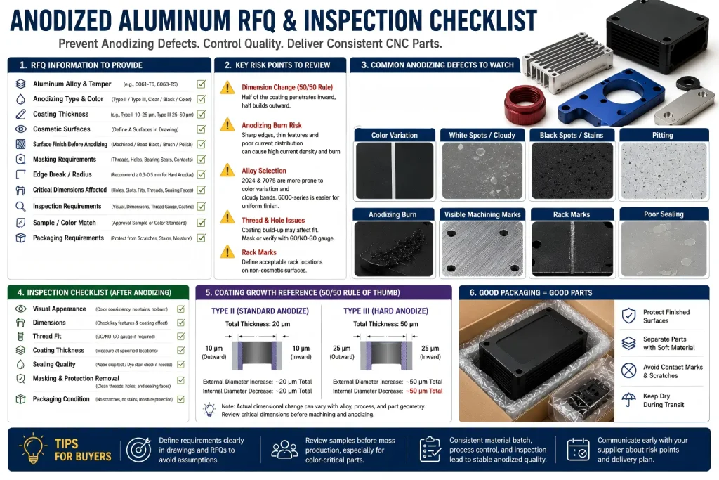
Inspection Checklist Before and After Anodizing
For CNC machined aluminum parts, inspection should not happen only after anodizing. Some defects must be caught before finishing.
Before Anodizing
Check:
- alloy grade
- material batch if color matching matters
- visible machining marks
- burrs and sharp edges
- surface contamination
- scratches and handling marks
- blind holes and trapped chip areas
- cosmetic faces
- masking requirements
- rack contact areas
- edge breaks on hard-anodized features
- critical dimensions affected by coating build-up
After Anodizing
Check:
- color consistency
- visible stains or spots
- pitting
- burn marks
- rack mark location
- thread fit
- critical dimensions
- sealing condition if required
- scratches after handling
- packaging condition
For cosmetic aluminum parts, inspection should compare the finished part against approved samples or agreed visual criteria when required.
Buyer Questions Before Quotation
Is anodizing supposed to hide scratches?
No. Anodizing usually does not hide scratches, tool marks, or poor surface preparation. It may make them more visible. If appearance matters, define the required pre-anodize surface finish.
Why do black anodized aluminum parts have color differences?
Color differences may come from alloy variation, material batch, surface roughness, oxide thickness, dye absorption, sealing, part geometry, and finishing lot differences. Critical cosmetic parts should be grouped and approved by sample when needed.
Can anodizing affect dimensions?
Yes. The oxide layer can affect holes, slots, threads, fits, and tight tolerance features. As a practical estimate, about half of the coating thickness may build outward from the original surface, so coating thickness should be reviewed before machining critical dimensions.
Why do anodized parts have rack marks?
Anodizing requires electrical contact, so rack marks may be necessary. The RFQ should define where rack marks are acceptable.
Why do sharp edges burn during anodizing?
Sharp edges can concentrate current during anodizing. This is especially important for hard anodizing or thick coating requirements. A small edge break or radius can help reduce burn and edge chipping risk when the design allows it.
Should threads be masked before anodizing?
It depends on the thread size, coating thickness, assembly requirement, and inspection method. Functional threads may need masking, post-anodize checking, or GO/NO-GO gauge inspection.
Is 7075 good for anodizing?
7075 can be anodized, but uniform cosmetic color may be more difficult than with alloys such as 6061 or 6063. If appearance matters, review samples and finishing requirements before production.
Is 6061 better than 7075 for cosmetic anodizing?
Often yes for appearance consistency. 7075 may be better for strength, but 6061 is usually easier to control for general colored anodizing and cosmetic consistency.
How Rapid Efficient Reviews Aluminum Anodizing RFQs
Rapid Efficient supports custom CNC machining projects for aluminum parts with anodizing, bead blasting, brushing, polishing, masking, and inspection requirements. Before quotation, we can review alloy selection, machining strategy, surface finish, cosmetic faces, masking areas, rack mark locations, thread protection, tolerance risks, inspection requirements, packaging, and delivery schedule.
For anodized aluminum CNC parts, we recommend sending:
- 2D drawing
- 3D CAD file
- aluminum alloy grade
- anodizing type and color
- cosmetic surface requirements
- coating thickness requirement if applicable
- masking requirement
- thread and hole protection notes
- edge break or radius requirements for hard anodizing
- tolerance and inspection requirements
- sample or color matching requirement
- annual or batch quantity
If your drawing only says “black anodized” or “clear anodized,” send the file before production so the finish requirement can be reviewed clearly.
Material certificates, CMM reports, and inspection reports are available depending on project requirements. For suitable rapid delivery projects, lead times may be as fast as 3–7 working days after drawing review and production confirmation.
If you are not sure whether your aluminum CNC part should use clear anodizing, black anodizing, hard anodizing, masking, bead blasting, or post-anodize inspection, send your drawing to Rapid Efficient for anodizing and RFQ review before production.