A threaded hole is any hole with internal threads. A tapped hole is a threaded hole made by a tapping operation.
So the practical answer is:
All tapped holes are threaded holes, but not all threaded holes are necessarily made by tapping.
For simple CNC parts, the two terms are often used casually. But on engineering drawings, RFQs, inspection reports, and production notes, the difference can matter. A buyer usually cares about the final threaded feature: thread size, thread depth, tolerance class, blind or through-hole design, strength, inspection method, and whether the thread will assemble correctly.
The manufacturer cares about how the thread will be produced: tapping, thread milling, thread forming, inserts, or another process depending on material, hole depth, tolerance, and quantity.
For CNC machined parts, Rapid Efficient generally recommends specifying the thread requirement clearly first. The manufacturing method should be controlled only when it affects function, quality, cost, or customer approval.
Simple Answer for Buyers
| Question | Better Answer |
|---|---|
| Is a tapped hole the same as a threaded hole? | Not exactly. A tapped hole is one type of threaded hole. |
| Which term should be used on a drawing? | Usually “threaded hole” with exact thread size, depth, and class. |
| When should “tapped” be written? | When tapping is specifically required or expected. |
| Can a threaded hole be made without tapping? | Yes. It can be made by thread milling, forming, inserts, or other methods. |
| What causes most RFQ problems? | Missing thread depth, blind-hole clearance, tolerance class, or inspection notes. |
| Which term is safer for CNC RFQs? | “Threaded hole” plus complete thread specification. |
The most common mistake is writing only:
Tap hole
or:
Threaded hole
without enough detail.
That may look simple, but it leaves important questions unanswered.
What Is a Threaded Hole?
A threaded hole is a hole with internal threads that can accept a screw, bolt, threaded pin, fitting, insert, or other mating component.
The term describes the final feature, not necessarily the manufacturing method.
A threaded hole can be produced by:
- cutting taps
- form taps
- thread milling
- single-point internal threading
- thread inserts
- molded or cast-in thread features followed by machining
- secondary operations after CNC machining
For CNC buyers, “threaded hole” is often the better functional term because it focuses on what the part must do.
A complete threaded hole requirement should answer:
- What is the thread size?
- Is it metric, UNC, UNF, NPT, BSP, or another standard?
- Is the hole blind or through?
- What is the required thread depth?
- What is the drill depth if the hole is blind?
- What tolerance class or fit is required?
- Is thread inspection required?
- Is the thread used for assembly, sealing, alignment, or load-bearing?
- Is a thread insert required?
- Is substitution of thread process allowed?
If these details are missing, the part may be machinable but still fail assembly or inspection.
Thread class should also be specified carefully. For many standard industrial CNC parts, a commercial internal thread class such as Metric 6H or Unified 2B is usually sufficient. These fits allow reliable assembly while keeping tapping, gauging, and production control practical.
Tighter thread classes, such as Metric 4H/5H or Unified 3B, should not be applied automatically just because the CAD software offers them. A tighter class can require more careful tool selection, more frequent inspection, better process stability, and higher rejection risk, especially in stainless steel, titanium, hard metals, or deep blind holes.
For normal brackets, covers, housings, mounting plates, and general equipment components, over-specifying thread class can add cost without improving real assembly performance. Use tighter thread classes only when the mating hardware, vibration, sealing, alignment, customer standard, or inspection requirement truly justifies them.
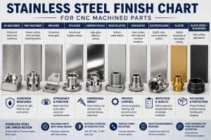
For related finishing and tolerance planning, review the CNC surface finishes guide and CNC machining tolerances guide.
What Is a Tapped Hole?
A tapped hole is a threaded hole produced by using a tap. The tap cuts or forms the internal thread after a drilled hole has been prepared.
Tapping is common because it is efficient, familiar, and cost-effective for many hole sizes and materials.
Tapped holes are often used in:
- brackets
- housings
- covers
- plates
- fixtures
- spacers
- mounting blocks
- electronic enclosures
- automation components
- stainless steel, aluminum, brass, copper, and plastic CNC parts
But “tapped hole” is a process description. It does not automatically define the full thread requirement.
A drawing note such as:
M6 tapped hole
is better than nothing, but it may still be incomplete.
A safer note might be:
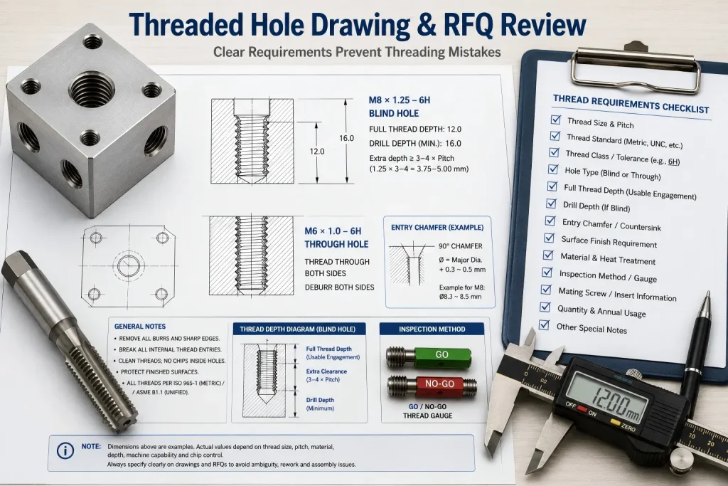
M6 × 1.0, 6H, thread depth 12 mm, blind hole, drill depth 16 mm.
For production and inspection, this gives the supplier a much clearer target.
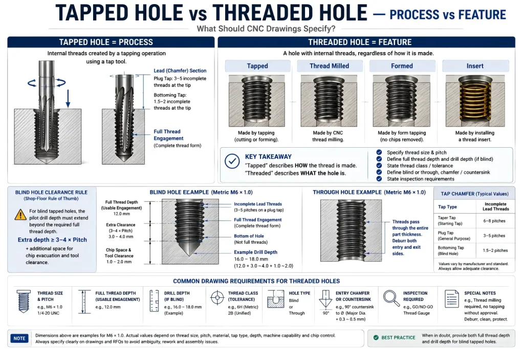
Tapped Hole vs Threaded Hole: Process vs Feature
The simplest way to understand the difference is this:
| Term | What It Describes | CNC Meaning |
| Threaded hole | The finished internal thread feature | The hole must accept the specified mating screw, bolt, or fitting. |
| Tapped hole | The method used to create the internal thread | The thread is made using a tap. |
| Thread milled hole | A threaded hole made by thread milling | Often useful for larger holes, hard materials, or better process control. |
| Form-tapped hole | A thread formed without cutting chips | Often used in ductile materials with correct pilot hole control. |
| Inserted thread | A threaded hole using a thread insert | Used for repair, wear resistance, soft materials, or stronger threads. |
This distinction matters because a buyer may not care whether the supplier taps or thread mills the hole, as long as the final thread meets the drawing. But in some materials or geometries, the process choice can affect cost, delivery time, thread quality, burr risk, tool breakage, and inspection.
For a deeper process comparison, see thread milling vs tapping.
When the Difference Matters in CNC Machining
For simple through holes in aluminum plates, the difference between “tapped hole” and “threaded hole” may not create much confusion. The supplier can usually infer the process.
But the difference becomes important when the part has:
- blind holes
- deep threaded holes
- small threads
- stainless steel or titanium threads
- thin walls near the thread
- tight positional tolerances
- sealing threads
- cosmetic surfaces near the hole
- threads close to edges
- hard material
- expensive parts where tap breakage is risky
- high quantity production
- assembly-critical thread engagement
In these cases, a vague note can cause real problems.
For example, a blind M3 thread in stainless steel is not the same as a through M8 thread in aluminum. Both may be called “tapped holes,” but the machining risk, tool selection, thread depth, chip evacuation, inspection, and failure cost are very different.
Blind Holes Create the Most Confusion
Blind threaded holes cause more RFQ and production mistakes than many buyers expect.
A blind hole does not pass completely through the part. The thread must stop inside the material, which means the machinist must control:
- drilled hole depth
- usable thread depth
- tap clearance
- bottom chamfer
- chip space
- tool approach
- thread gauge engagement
- risk of tool breakage
- minimum remaining wall thickness
The biggest issue is that drill depth and thread depth are not the same thing.
If the drawing only says:
M6 tapped hole, depth 12 mm
the supplier may need to clarify whether 12 mm means:
- hole depth
- full thread depth
- usable thread depth
- minimum thread engagement
- drill depth before tapping
- tap depth including incomplete bottom threads
A better drawing note separates these requirements.
A useful shop-floor rule is to leave clearance beyond the required full thread depth. Standard cutting taps do not create full thread form at the very tip. A plug tap commonly has several incomplete lead threads before the full profile is formed, while a bottoming tap still needs a short incomplete lead section.
For blind tapped holes, this means the drilled pilot hole should usually extend beyond the required full thread depth. As a practical RFQ rule, designers often allow extra depth of at least 3 to 4 times the thread pitch, plus enough space for chip control and tool clearance when the geometry allows it.
If the part has a thin wall, shallow boss, sealed bottom, or very limited packaging space, this clearance may not be available. In that case, the thread process should be reviewed instead of assuming standard tapping. Thread milling may be safer for some blind holes because it can control the thread profile closer to the bottom and reduce the risk of tap breakage in expensive CNC parts.
For process selection, see thread milling vs tapping.
| Drawing Requirement | Why It Matters |
| Thread size | Defines the mating screw or bolt. |
| Thread pitch | Prevents mismatch between coarse and fine threads. |
| Thread class | Defines fit and inspection expectation. |
| Full thread depth | Defines usable thread engagement. |
| Drill depth | Provides clearance for tool tip and incomplete threads. |
| Blind or through | Affects machining process and inspection. |
| Chamfer or countersink | Helps assembly and reduces burrs. |
| Inspection method | Prevents disagreement after production. |
For blind holes, the safest RFQ should include both thread depth and drill depth when the design requires control.
Drawing Notes That Prevent Thread Mistakes
The best way to prevent thread mistakes is to write the hole requirement clearly before quotation.
| Buyer Intention | Better Drawing or RFQ Note |
| Standard metric thread | M6 × 1.0 threaded hole, 6H, thread depth 12 mm. |
| Blind tapped hole | M6 × 1.0, 6H, blind, full thread depth 12 mm, drill depth 16 mm. |
| Through threaded hole | M6 × 1.0 through threaded hole, deburr both sides. |
| UNC thread | 1/4-20 UNC-2B threaded hole, depth 0.50 in. |
| Fine thread | M8 × 1.0 threaded hole, class 6H, confirm mating screw. |
| Thread insert required | Install stainless steel thread insert per drawing requirement. |
| Thread process controlled | Thread milling required; no tapping without approval. |
| Inspection required | GO/NO-GO thread gauge inspection required. |
| Cosmetic surface near thread | Protect visible surface; no raised burr around threaded hole. |
| Sealing thread | Confirm thread standard, seal type, and inspection method before production. |
For CNC RFQs, a complete thread note is usually more useful than simply writing “tap hole.”
For broader part design planning, review the CNC machining design guide before locking threaded features, wall thickness, blind-hole depth, and assembly clearance.
When Tapping Is Usually Acceptable
Tapping is often practical when:
- the thread size is common
- the material is not too difficult
- the hole is not extremely deep
- the quantity supports efficient cycle time
- tool access is straightforward
- the tolerance requirement is standard
- the thread is not close to a fragile edge
- broken tap risk is manageable
- the part cost is not extremely high
- the customer does not require thread milling or inserts
Tapping can be efficient for many aluminum, brass, steel, stainless steel, and plastic parts. It is not a low-quality method by default.
The risk is not tapping itself. The risk is using tapping when the geometry, material, or thread requirement makes another method safer.
When a Threaded Hole Should Not Simply Be “Tapped”
Some threaded holes should be reviewed before assuming a tapping process.
| Condition | Why Tapping May Need Review |
| Deep blind hole | Chip evacuation and bottom clearance may be difficult. |
| Small thread in stainless steel | Tap breakage risk can be high. |
| Expensive finished part | Broken tap removal may damage the part. |
| Large thread | Thread milling may be more flexible. |
| Hard material | Tool wear and breakage risk increase. |
| Thin wall | Thread load and distortion risk need review. |
| Thread near edge | Breakout or deformation may occur. |
| Tight position tolerance | Process sequence and inspection need control. |
| Short thread engagement | Assembly strength may be insufficient. |
| Sealing thread | Thread form and inspection must match sealing method. |
If the drawing only says “tapped,” the supplier may quote the fastest process. If the part requires a controlled internal thread, the RFQ should make that clear.
Thread Milling vs Tapping in This Decision
Thread milling and tapping can both produce internal threads, but they behave differently.
Tapping uses a tap that matches the thread size. It is often fast and cost-effective.
Thread milling uses a CNC toolpath to cut the thread profile. It can offer more control in some cases, especially for larger holes, difficult materials, blind holes, or expensive components where tool breakage risk needs to be reduced.
| Factor | Tapping | Thread Milling |
| Cycle time | Often faster | Often slower |
| Tool cost | Usually lower | Usually higher |
| Flexibility | One tap per thread size and pitch | One tool may cover multiple sizes within limits |
| Blind hole control | Can be limited near bottom | Often better control |
| Broken tool risk | Broken tap can be difficult to remove | Broken tool may be easier to recover from |
| Large threads | May require large taps | Often practical |
| Small holes | Often practical | May be limited by tool size |
| Hard materials | Higher breakage risk | Often safer when reviewed correctly |
| Thread quality control | Good when process is stable | Good when machine and toolpath are controlled |
This does not mean thread milling is always better. It means the process should match the thread requirement, material, and part risk.
For a full process comparison, see thread milling vs tapping.
Material Effects: Aluminum, Stainless Steel, Brass, and Plastic
The same thread note can behave differently depending on material.
Aluminum
Aluminum is usually easier to tap than stainless steel, but soft aluminum threads can wear, strip, or gall if the engagement length is too short or the assembly is repeated often.
Thread inserts may be useful when:
- repeated assembly is expected
- screw load is high
- soft material may strip
- repairability matters
- the customer specifies insert strength
Stainless Steel
Stainless steel threaded holes require more attention to cutting speed, lubrication, work hardening, and chip evacuation. Small blind tapped holes in stainless steel can be risky if the thread depth is aggressive or access is poor.
For material-specific machining behavior, see the stainless steel CNC machining guide.
Brass and Copper
Brass can often machine cleanly, but exact alloy matters. Copper can be gummy and may create burrs or poor chip control if tooling and parameters are not suitable.
Engineering Plastics
Plastic threaded holes may deform, crack, or strip if the thread design ignores material creep, assembly torque, or wall thickness. Inserts are often reviewed for repeated assembly or stronger threads.
Inspection: How Threaded Holes Are Verified
Threaded holes are commonly inspected using thread gauges, pin gauges, visual checks, CMM location checks, or functional assembly tests depending on project requirements.
Common inspection points include:
- thread size
- thread pitch
- thread depth
- hole position
- perpendicularity if required
- burrs at entry and exit
- chamfer condition
- thread damage
- insert installation
- fit with mating screw or bolt
For many standard internal threads, GO/NO-GO thread gauges are used to confirm thread acceptance. However, inspection method should match the drawing requirement and customer expectation.
A CMM may verify hole position, but it does not automatically prove that the internal thread form is acceptable. Thread inspection and dimensional inspection should not be confused.
For tolerance and inspection planning, see the CNC machining tolerances guide.
Surface Finish and Burr Control Around Threaded Holes
Threaded holes often create burrs at the hole entrance, exit side, counterbore, or intersecting features.
Burrs can cause:
- poor screw seating
- cosmetic rejection
- assembly difficulty
- thread gauge failure
- damaged mating hardware
- loose debris inside the part
- contamination risk in clean assemblies
A drawing note such as:
Deburr sharp edges
may be enough for general parts, but it may be too vague for cosmetic, sealing, medical, optical, or clean equipment components.
One common assembly problem is that the threaded hole passes a basic thread gauge check, but the mating plate, flange, or bracket still does not sit fully flush. The cause is often a raised entry burr or slightly lifted first thread crest around the hole mouth.
This can happen when tapping or thread milling displaces material at the entry face. The burr may be small, but on a flat mounting surface it can create a visible gap, affect seating, or damage a mating surface during assembly.
For higher-requirement threaded holes, the drawing should define an entry chamfer or countersink instead of relying only on a general deburr note. A practical rule is to specify a 90° or 120° entry chamfer with a diameter equal to or slightly larger than the thread major diameter, often around Major Diameter + 0.3 mm to 0.5 mm when the design allows it.
This helps remove the raised entry burr, improves screw starting, protects flat mating faces, and gives inspection a clearer acceptance boundary.
Better notes may include:
- deburr threaded holes
- remove loose chips from blind holes
- protect cosmetic surfaces
- no raised burr around mating face
- define entry chamfer or countersink diameter
- clean internal threads before packing
- plug or protect threaded holes before surface finishing when required
For finishing decisions, see the CNC surface finishes guide.
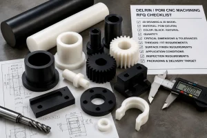
RFQ Checklist for Threaded Holes
Before sending a threaded part for quotation, check whether the RFQ includes:
| RFQ Item | Why It Matters |
| Thread standard | Prevents metric/imperial mismatch. |
| Thread size and pitch | Defines mating hardware. |
| Thread depth | Controls usable engagement. |
| Drill depth for blind holes | Avoids bottoming and incomplete thread confusion. |
| Blind or through hole | Affects machining and inspection. |
| Thread class or fit | Defines acceptance requirement. |
| Material | Affects process risk and tool selection. |
| Surface finish | May affect burrs, masking, or cosmetic surfaces. |
| Entry chamfer or countersink | Prevents raised burrs from affecting assembly faces. |
| Insert requirement | Changes sourcing and process planning. |
| Inspection method | Prevents acceptance disputes. |
| Mating hardware | Helps verify assembly fit. |
| Quantity | Affects process choice and tooling strategy. |
A clean RFQ can reduce rework, late clarification, and production delays.
Buyer Questions Before Quotation
Is a tapped hole always threaded?
Yes. A tapped hole is a threaded hole made using a tap.
Is every threaded hole tapped?
No. A threaded hole can also be made by thread milling, forming, inserts, or other methods depending on material and design.
Should I write tapped hole or threaded hole on a drawing?
Usually, write the exact thread requirement. “Threaded hole” plus size, pitch, class, and depth is clearer than only writing “tapped hole.”
What is the biggest mistake with blind tapped holes?
The biggest mistake is not separating full thread depth from drill depth. Blind holes need clearance for tool geometry, incomplete bottom threads, chip space, and tool movement.
How much extra drill depth does a blind tapped hole need?
It depends on thread size, pitch, tap type, material, chip control, and tool access. As a practical starting point, many designs allow extra depth of at least 3 to 4 times the thread pitch beyond the required full thread depth when geometry allows it.
Can a supplier choose thread milling instead of tapping?
Often yes, if the final thread meets the drawing. But if the process matters, the RFQ should state whether tapping, thread milling, or another method is required.
Do threaded holes need inspection?
For functional or customer-controlled parts, yes. Thread gauge inspection, visual review, hole position inspection, and assembly checks may be required depending on the drawing.
Is 3B or 4H thread class always better?
No. Tighter thread classes can increase tooling cost, inspection frequency, and rejection risk. For many standard CNC parts, commercial 2B or 6H internal threads are more practical unless the application truly requires tighter fit control.
How Rapid Efficient Reviews Threaded Hole RFQs
Rapid Efficient supports custom CNC machining projects with threaded holes, tapped holes, thread milling, inserts, and assembly-critical features. Before quotation, we can review thread size, thread depth, blind-hole clearance, material behavior, burr risk, surface finish, inspection requirements, packaging, and delivery schedule.
For threaded CNC parts, we recommend sending:
- 2D drawing
- 3D CAD file
- thread size and pitch
- thread depth and drill depth if blind
- thread class or fit requirement
- material grade
- surface finish requirement
- entry chamfer or countersink requirement
- inspection or gauge requirement
- mating screw, bolt, fitting, or insert information
- annual or batch quantity
If your drawing only says “tap hole” or “threaded hole,” send the file before production so the thread requirement can be reviewed clearly.
Material certificates, CMM reports, and inspection reports are available depending on project requirements. For suitable rapid delivery projects, lead times may be as fast as 3–7 working days after drawing review and production confirmation.
If you are not sure whether your part should use tapping, thread milling, thread forming, or inserts, send your drawing to Rapid Efficient for threaded hole and RFQ review before production.