A threaded hole can be the last operation on a CNC machined part.
That is exactly why it can be expensive.
If a tap breaks inside a nearly finished aluminum housing, stainless-steel manifold, copper connector, or precision fixture, the problem is not just the broken tool. The part may already include roughing, finishing, tight bores, surface-sensitive faces, datum-related features, and inspection work.
At that point, one failed thread can turn a good part into scrap.
Tapping and thread milling can both produce reliable threads. The right choice depends on the thread size, hole depth, blind-hole condition, material, quantity, tool access, machine capability, surface finish, inspection method, and the cost of failure.
The useful question is not:
Is thread milling better than tapping?
The useful question is:
Which threading process protects this specific part from the most likely failure mode?
Rapid Efficient supports custom CNC machining projects involving threaded holes, blind holes, precision bores, milled features, turned features, and post-processing requirements. Before quotation, we review the drawing together with the material grade, thread size, thread depth, hole condition, tolerance requirements, surface-finishing route, inspection method, quantity, and delivery schedule.
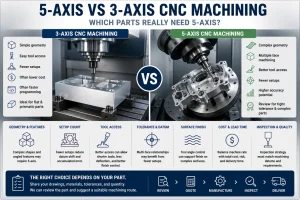
Start with the Failure Mode, Not the Tool Name
A standard tapped through-hole in aluminum is not the same risk as a deep blind thread in 304 stainless steel.
A large thread in a low-volume prototype is not the same decision as a small repeated thread in a production batch.
A thread added early in the machining sequence is not the same as a thread added after several expensive setups.
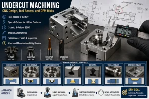
Before choosing tapping or thread milling, identify the real failure mode:
- Will chips pack at the bottom of a blind hole?
- Is there enough bottom clearance for the tap chamfer?
- Is the material likely to work-harden or smear?
- Is the pilot hole tightly controlled?
- Would a broken tap destroy the part?
- Does the thread need go/no-go gauge verification?
- Will anodizing, plating, coating, or passivation affect the final thread?
- Is the thread near a sealing surface, bearing feature, or critical datum?
- Does the drawing define thread depth clearly?
- Is the part expensive before the threading operation begins?
Once the failure mode is clear, the process decision becomes much easier.
What Actually Changes Between Tapping and Thread Milling
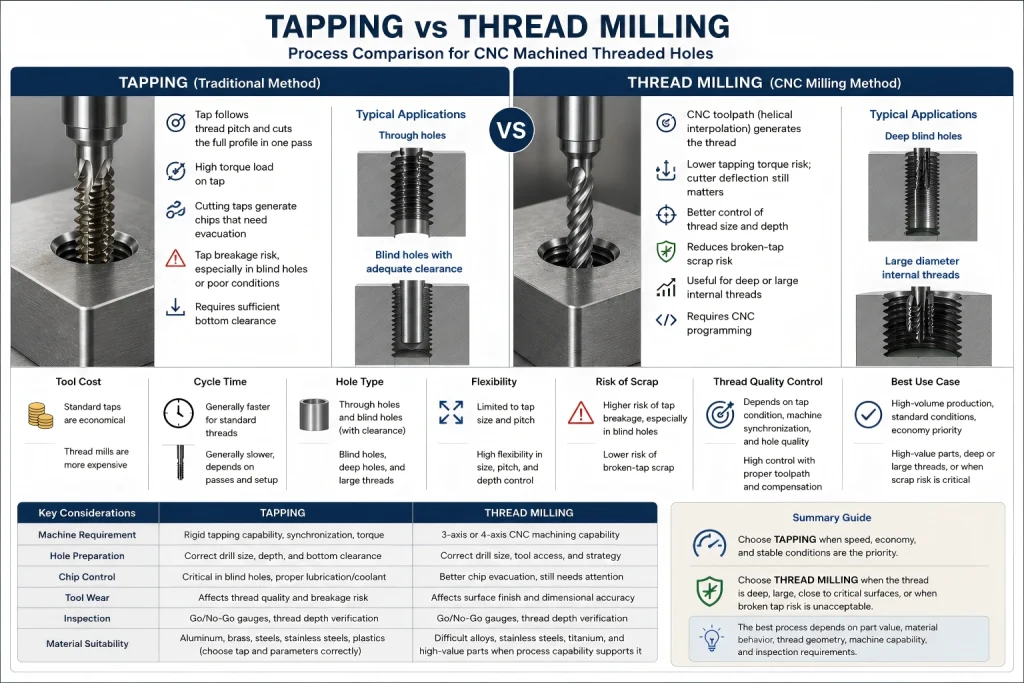
Tapping creates a thread by driving a tap into a pre-drilled hole. The tap follows the thread pitch directly and cuts or forms the thread as it advances.
Thread milling also starts with a prepared hole, but the cutter does not follow the thread like a tap. The CNC program uses circular ramping or helical interpolation to generate the thread profile. The tool moves around the hole while advancing in Z according to the thread pitch.
This changes where the risk sits.
Tapping Concentrates Risk in Torque and Synchronization
Tapping depends on synchronized spindle rotation and Z-axis feed.
In a rigid or synchronous tapping cycle, the machine must control spindle rotation, feed, reversal, and depth consistently. If the hole bottom, chip packing, lubrication, tap wear, or machine synchronization is not controlled, the torque load can rise quickly.
When a tap breaks, removal can be difficult. In some cases, the part cannot be recovered without EDM removal, oversized repair threads, customer approval, or complete replacement.
Thread Milling Concentrates Risk in Toolpath and Deflection
Thread milling shifts the process risk toward path accuracy, radial engagement, tool deflection, programming, and inspection.
The cutter is usually smaller than the hole. This may reduce broken-tool recovery risk, but it does not make the operation automatically safe.
If the toolpath, cutter reach, run-out, radial cutting load, or compensation is wrong, the thread may become tapered, undersized, oversized, rough, or inconsistent through the required depth.
Neither method is automatically better.
The safer method is the one that matches the thread geometry, material behavior, machine capability, and inspection requirement.
Threading Risk Decision Map
| Threading Situation | Tapping Usually Makes Sense When… | Thread Milling Usually Deserves Review When… | Main Risk to Control |
|---|---|---|---|
| Standard through-hole thread | The material is suitable, the thread size is common, and chip evacuation is predictable | Thread quality needs fine adjustment or material behavior is unstable | Chip evacuation, tool wear, gauge acceptance |
| Blind-hole thread | There is enough drill depth, bottom clearance, lubrication, and chip control | The thread must approach the bottom more closely or tap breakage risk is high | Bottom clearance, trapped chips, tap breakage |
| Large internal thread | Machine torque and tap cost are acceptable | A large tap is expensive, high-torque, or risky for the machine and part | Torque load, tool cost, part recovery |
| Small internal thread | A standard tap is stable and tool access is good | The thread is in high-value material or breakage would be difficult to recover | Tool fragility, run-out, inspection |
| Expensive near-finished part | Tapping is already proven and scrap risk is low | A broken tap would destroy too much machining value | Late-stage scrap risk |
| Stainless steel thread | Lubrication, tap style, chip control, and depth are stable | Work-hardening, chip packing, or thread quality needs better control | Heat, work hardening, tool wear |
| Aluminum thread before anodizing | Thread fit and post-finish condition are already controlled | Coating thickness, masking, or post-finish verification is uncertain | Thread fit after finishing |
| Form-tapped thread | Material is ductile and pilot-hole control is reliable | Pilot-hole variation is hard to control or thread percentage is critical | Forming torque, incomplete thread crest |
| Multiple thread sizes or directions | Dedicated taps are already available and efficient | One thread mill can cover compatible sizes or right/left-hand threads | Tool availability, programming |
| Tight thread inspection requirement | Tapping gives stable go/no-go gauge results | Pitch diameter or fit needs adjustable CNC control | Gauge depth, pitch diameter, repeatability |
This map is not a universal process recipe.
It is a way to identify which risk matters before machining begins.
Where Tapping Wins
Tapping is often the most efficient choice for standard threaded holes.
It can be the better route when:
- The thread size is common
- The material is suitable
- The hole depth is reasonable
- The thread is not too close to the bottom of a blind hole
- Chip evacuation is predictable
- Tap life is stable
- Machine synchronization is reliable
- Quantity supports a fast repeatable operation
- Gauge acceptance is proven
- The thread is not the highest-risk final operation on the part
Tapping is especially practical for simple through-holes and common blind holes where the process is already stable.
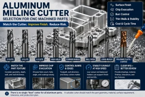
Common tap-related choices include:
- Spiral point taps for through holes where chips can move forward
- Spiral flute taps for blind holes where chips need to move upward
- Form taps for selected ductile materials when chip-free thread forming is suitable
- Bottoming taps when more complete threads are required near the bottom of a blind hole
However, tapping becomes risky when the hole condition is treated casually.
A blind hole with insufficient bottom clearance can force the tap into packed chips or the hole bottom.
A worn tap may produce rough, oversized, undersized, or inconsistent threads.
A tap used in difficult material without proper lubrication and chip control may break before the operator sees an obvious warning sign.
Where Thread Milling Protects the Part
Thread milling becomes attractive when the thread carries higher manufacturing risk.
It may be worth reviewing when the part includes:
- Large internal threads
- Deep blind holes
- Expensive material
- Difficult-to-machine alloys
- Short-run parts with varied thread requirements
- Tight thread quality requirements
- Threads close to sealing surfaces
- Threads near critical datum features
- Left-hand and right-hand thread requirements
- High scrap risk if a tap breaks
- Parts that are nearly complete before threading
Thread milling gives the CNC program more control over how the thread is generated.
Depending on the tool, machine, and geometry, the process may allow adjustment of:
- Thread depth
- Pitch diameter
- Radial engagement
- Entry and exit strategy
- Multiple radial passes
- Spring passes or light finishing passes
- Direction of cut
- Approach near the bottom of a blind hole
This flexibility can reduce risk when tapping would load the tool too aggressively.
But thread milling is not a magic solution.
Because the cutter removes material through radial engagement, tool deflection can affect thread size. This becomes more important in tough materials, deeper threads, small tools, long overhangs, and high thread-quality requirements.
If the process is not controlled, the thread may appear acceptable near the entrance but become tight deeper in the hole.
For deeper or higher-risk thread milling, the process plan may need:
- Reduced radial engagement
- Multiple radial passes
- A spring pass or light finishing pass
- Shorter tool overhang
- Rigid toolholding
- Toolpath verification
- Thread-gauge inspection through the required thread depth
Thread milling reduces the classic broken-tap-in-hole risk, but it still requires disciplined process control.
Blind Holes Are the Real Test
Blind holes expose the difference between tapping and thread milling quickly.
A through-hole gives chips somewhere to go. A blind hole does not.
That means thread depth, drill depth, bottom clearance, chip evacuation, coolant, lubrication, tap chamfer length, and inspection method become much more important.
With tapping, the process must confirm:
- Drill depth
- Required thread depth
- Tap chamfer length
- Bottom clearance
- Chip evacuation direction
- Lubrication or coolant
- Tap wear
- Thread-gauge requirement
- Whether the tap may hit the bottom
- Whether chips may become trapped
With thread milling, the process must confirm:
- Pre-drilled hole size
- Thread mill reach
- Tool diameter
- Circular interpolation clearance
- Entry and exit path
- Thread depth
- Bottom relief
- Chip evacuation
- Program verification
- Gauge inspection through the required depth
A blind hole that looks safe in CAD may still fail in production if the drawing does not define enough drill depth, relief, or inspection detail.
For blind holes, deep holes, fitted bores, H7 holes, and thread-related tolerance planning, review our CNC machining tolerances guide.
The Pilot Hole Decides More Than Buyers Expect
Thread quality does not begin when the tap or thread mill enters the part.
It begins with the pilot hole.
A threaded hole can fail even when the correct threading tool was selected if the pilot hole is wrong.
Review:
- Pilot-hole diameter
- Hole straightness
- Hole depth
- Drill wear
- Tool run-out
- Hole surface condition
- Work-hardened or smeared material
- Chips left in the hole
- Burrs at the thread entrance
- Lubrication or coolant delivery
- Thread-gauge requirement
If the pilot hole is too small, tapping torque may rise and breakage risk increases.
If the pilot hole is too large, thread engagement may be insufficient.
If the hole is tapered, rough, work-hardened, or contaminated with chips, the threading operation may fail even when the tap or thread mill is suitable.
Form Taps Need Even Tighter Pilot-Hole Control
Form taps deserve special attention.
A cutting tap removes material to create the thread. A form tap displaces material instead of cutting chips.
Because the material must flow into the thread profile, the pre-drilled hole usually needs a larger and more tightly controlled size than a comparable cutting-tap hole.
If the pilot hole is too small, forming torque can rise sharply. The tap may wear, seize, or break.
If the pilot hole is too large, the formed thread may have incomplete crest formation and may fail assembly or gauge expectations.
Before using a form tap, review:
- Material ductility
- Recommended pilot-hole size
- Pilot-hole tolerance
- Drill wear
- Hole straightness
- Lubrication
- Thread percentage requirement
- Thread-gauge acceptance
- Whether the material is suitable for cold forming
Form tapping can be effective in suitable ductile materials, but it is less forgiving of pilot-hole variation than many buyers expect.
Materials Change the Threading Decision
The same thread size can behave very differently in different materials.
Aluminum Alloys
Aluminum is generally easier to thread than stainless steel, but soft material behavior can still create issues.
Review:
- Thread strength
- Burr formation
- Form tapping suitability
- Chip control
- Surface finish
- Anodizing allowance
- Thread inserts when required
For anodized aluminum, thread fit should be reviewed before finishing. Masking, post-finish verification, or controlled thread recovery may be required depending on the drawing.
Stainless Steel
Stainless steel can increase tapping risk because of work hardening, tool wear, heat, and chip-control challenges.
Review:
- Sharp tool condition
- Lubrication
- Tap style
- Hole depth
- Chip evacuation
- Thread-gauge acceptance
- Passivation requirement
- Burr control around thread entrances
For 304 stainless steel, repeated rubbing or poor chip evacuation around holes and threads may increase work-hardening risk.
Copper and Brass
Copper may be soft, ductile, and prone to burrs, smearing, or thread deformation depending on the grade.
Brass may be easier to thread depending on the grade, but lead-free or application-specific brass may behave differently.
Review:
- Burrs at thread entrance
- Chip control
- Thread surface quality
- Conductive contact areas
- Plating or anti-oxidation requirements
- Packaging protection
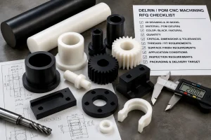
Engineering Plastics
Engineering plastics create different thread risks from metals.
Review:
- Material flexibility
- Thread strength
- Insert requirements
- Clamping deformation
- Thermal movement
- Dimensional recovery
- Thread-gauge timing
- Risk of over-tightening during assembly
Plastic threads should not be judged with the same assumptions used for rigid metal parts.
For broader material behavior, review our CNC machining materials guide.
Surface Finishing Can Change Thread Fit
Threading does not always end when machining ends.
Anodizing, hard anodizing, plating, powder coating, painting, passivation, cleaning, heat treatment, and packaging may all affect threaded features.
Examples include:
- Anodizing may tighten aluminum internal threads.
- Hard anodizing may require masking or post-finish verification.
- Plating may change thread fit depending on thickness and coverage.
- Powder coating can interfere with threaded holes if masking is not controlled.
- Passivation does not fix poor thread geometry or trapped chips.
- Cleaning and rinsing are important for blind threaded holes.
- Packaging must protect thread entrances from impact, scratches, and contamination.
Before production, the drawing should clarify whether the thread requirement applies:
- Before finishing
- After finishing
- On a masked feature
- After thread-gauge verification
- After cleaning and drying
- After customer-specified inspection
For post-processing risks around threads, holes, coatings, masking, and final inspection, review our CNC surface finishes guide.
Inspection: Do Not Skip the Gauge
A thread may look acceptable and still fail inspection.
The inspection method should match the thread function.
Depending on the project, inspection may include:
- Go/no-go thread gauges
- Pin gauges for pilot holes
- Plug gauges
- Optical inspection
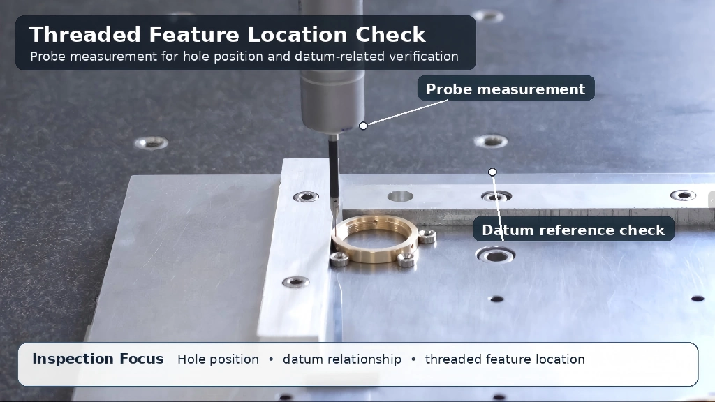
- CMM inspection for position
- Depth checks
- Burr inspection
- Visual inspection after finishing
- Fit checks with mating components
- Full-dimensional reports when required
A CMM may help verify threaded-hole position, datum relationships, and multi-feature location.
But a thread gauge is often the direct method for checking thread acceptance.
Do not replace functional thread verification with a measurement method that does not match the acceptance requirement.
For quality documentation, inspection reports, material certificates, and CMM-report options, review our quality assurance process.
The Real Cost Is Cycle Time Plus Failure Risk
Tapping is often efficient when the thread is standard, the material is stable, the hole is accessible, and the process is proven.
Thread milling may take more programming or cycle time, but it can reduce total risk when the thread is difficult or the part is expensive before threading.
The cost decision should include:
- Tooling cost
- Cycle time
- Setup time
- Programming time
- Tool availability
- Part value before threading
- Scrap risk
- Rework risk
- Gauge inspection
- Quantity
- Material behavior
- Delivery schedule
A low-cost tap operation can become expensive if one broken tap ruins a finished part.
A thread-milling operation can become unnecessary if the thread is simple, the material is easy, and tapping is already stable.
The best process is the one that balances cycle time, quality risk, inspection, and delivery reliability.
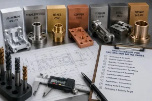
RFQ Checklist for Threaded CNC Parts
Before requesting a quote, prepare:
- 2D drawing
- 3D CAD file
- Material grade
- Quantity
- Thread standard
- Thread size
- Internal or external thread requirement
- Right-hand or left-hand thread
- Through-hole or blind-hole condition
- Hole depth
- Required thread depth
- Bottom clearance
- Pilot-hole requirement when specified
- Thread class or tolerance
- Surface-finish requirement
- Heat-treatment requirement
- Passivation, anodizing, plating, or coating requirement
- Thread-gauge requirement
- Mating component when available
- Inspection-report requirement
- Packaging requirement
- Target delivery schedule
If you are unsure whether the thread should be tapped or thread milled, identify the thread function and failure risk.
Examples include:
- Thread must hold repeated assembly.
- Thread is close to a sealing surface.
- Thread is near the bottom of a blind hole.
- Thread is in stainless steel or titanium.
- Thread is machined after expensive finishing operations.
- Broken tap removal would be unacceptable.
- Thread must be inspected with a customer-specified gauge.
These details help the machining team choose the safer route before production begins.
Threading Questions Buyers Usually Ask
Is thread milling stronger than tapping?
Not automatically.
Thread strength depends on material, thread engagement, pilot-hole size, thread form, tool condition, and inspection acceptance.
Thread milling may provide better control in selected cases, but the thread design and material still control the final performance.
Is tapping faster than thread milling?
Often, yes.
Tapping can be faster for many standard threaded holes, especially when the material, quantity, and hole condition are suitable.
Thread milling may be preferred when flexibility, risk reduction, thread quality control, or broken-tool recovery matters more than cycle time alone.
Should blind holes be tapped or thread milled?
It depends on bottom clearance, thread depth, material, chip evacuation, thread size, and scrap risk.
Tapping can work well when there is enough clearance and chip control.
Thread milling may be safer when the blind hole is deep, expensive, difficult to clean, or close to a critical surface.
Can one thread mill cut different thread sizes?
In some cases, yes.
A thread mill may cut multiple compatible thread sizes if the pitch and tool geometry allow it, and the tool does not exceed its cutting limits.
The process still requires correct programming, hole preparation, and inspection.
Are form taps better than cutting taps?
Not always.
Form taps can produce strong chip-free threads in suitable ductile materials, but they require tighter pilot-hole control and proper lubrication.
They should not be selected only because they avoid chips. The material, pilot-hole tolerance, thread percentage, and gauge requirement should be reviewed first.
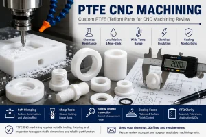
Upload Your Drawing for Threading Process Review
Send your 2D drawing, 3D CAD file, material grade, thread size, thread depth, hole type, tolerance requirements, surface finish, inspection needs, and expected quantity.
Our team will review whether tapping, thread milling, or another threading route is more suitable for your CNC machined part.
CTA Button: Upload Your Drawing
About Rapid Efficient
Rapid Efficient supports custom CNC machining projects for prototypes, low-volume parts, and production requirements.
With 18 years of high-precision CNC machining experience, our team reviews material behavior, machining strategy, tolerance risks, post-processing requirements, inspection methods, packaging conditions, and delivery schedules before quotation.
Our available capabilities include 4-axis, 5-axis, and multi-axis CNC machining, together with inspection equipment such as CMM, projectors, and spectrometers.
Depending on the actual part and project requirements, machining accuracy down to 0.01 mm and inspection accuracy down to 0.001 mm are available.
Rapid Efficient has obtained ISO 9001 and ISO 14001 certification.
We support projects across medical devices, communications equipment, optical components, drones, intelligent robotics, automotive applications, office automation, and other custom manufacturing requirements.