Choosing between CNC milling and CNC turning should not start with the machine name.
It should start with the part geometry.
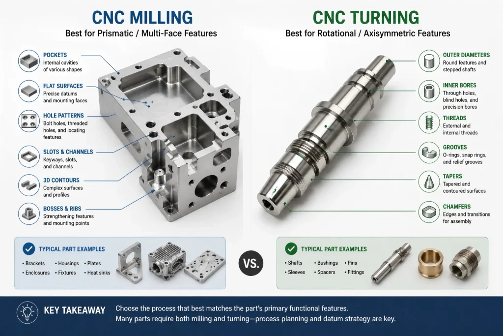
If the main shape is round, concentric, and built around a central axis, CNC turning may be the better starting point. If the part has pockets, flat faces, slots, side holes, complex contours, or multi-face features, CNC milling is usually more suitable.
Many custom CNC parts are not purely one or the other.
A shaft may need milled flats. A turned housing may need cross holes. A milled bracket may include precision bores. A cylindrical connector may require both turning and secondary milling.
The wrong process choice can increase setup time, tolerance risk, tool access problems, surface marks, and inspection cost.
Rapid Efficient supports custom CNC machining projects for prototypes, low-volume parts, and production requirements. Before quotation, we review the drawing together with the part geometry, material grade, tolerance requirements, surface finish, fixture strategy, inspection plan, and expected quantity.
The goal is not to force a part into milling or turning.
The goal is to choose the process route that controls function, cost, and delivery risk.
The Basic Difference Is Motion
CNC milling and CNC turning both remove material with cutting tools, but the motion is different.
In CNC turning, the workpiece rotates. The cutting tool moves against the rotating workpiece to create cylindrical, conical, grooved, threaded, or bored features.
In CNC milling, the cutting tool rotates. The workpiece is usually fixed or indexed while the cutter removes material from faces, pockets, slots, holes, contours, and multi-axis surfaces.
That motion difference controls what each process does best.
A round part is not automatically a turning part.
A flat part is not automatically a milling part.
The correct route depends on the features that control the final assembly.
Start with the Shape That Controls the Part
A simple way to review CNC milling vs CNC turning is to ask:
Which geometry must be most accurate for the part to function?
If the answer is a diameter, bore, concentric surface, thread, or round sealing face, turning may be the natural starting point.
If the answer is a flat mounting face, pocket, hole pattern, slot, datum surface, side feature, or complex contour, milling may control the function more directly.
For example:
- A spacer, bushing, shaft, sleeve, or round connector often begins with turning.
- A bracket, enclosure, mounting plate, housing, or heat sink often begins with milling.
- A valve body, optical mount, sensor housing, or precision connector may need both processes.
The process should follow the functional geometry, not the first view of the CAD model.
CNC Milling vs CNC Turning Decision Map
| Part Requirement | Better Starting Process | Why It Matters | Risk If Chosen Poorly |
|---|---|---|---|
| Round outer diameter | Turning | Rotating the workpiece helps control cylindrical surfaces efficiently | Milling a round profile may increase cycle time and surface variation |
| Concentric bore and outside diameter | Turning | Turning can maintain coaxial relationships in one setup when geometry allows | Repositioning may create run-out or alignment error |
| Flat mounting face | Milling | Milling controls flat faces, steps, pockets, and datum surfaces | Turning may require secondary setups or custom workholding |
| Pockets, slots, and side features | Milling | Rotating cutters access prismatic and multi-face features more directly | Turning alone cannot create many non-axisymmetric features |
| Cross holes or radial holes on a round part | Turning plus milling or live-tool turning | The main diameter may be turned, then side features require additional tool access | Extra setups may affect position, cost, and inspection |
| Thin-wall cylindrical part | Turning or combined route | Turning can be efficient, but wall movement and clamping must be reviewed | Excess clamping or poor sequence may distort the part |
| Complex enclosure or housing | Milling | Multi-face machining, pockets, screw bosses, and openings are usually milling-driven | Poor tool access can increase burrs, marks, and setup time |
| High-volume simple round parts | Turning | Turning can be efficient for repeated cylindrical features | Milling may create unnecessary cost |
| Prototype with mixed features | Process review required | The lowest-risk route depends on function, tolerance, and quantity | Choosing too early may create avoidable redesign or rework |
This table is a starting point.
The final process route should be reviewed against the drawing, material, tolerance requirements, surface finish, quantity, and inspection plan.
When CNC Turning Makes More Sense
CNC turning is usually a strong choice when the part is mainly controlled by rotational features.
Typical turned parts include:
- Shafts
- Bushings
- Spacers
- Sleeves
- Pins
- Nozzles
- Fittings
- Round connectors
- Cylindrical housings
- Threaded inserts
- Valve components
- Bearing-related parts
Turning is especially useful when the design requires:
- Controlled outside diameter
- Controlled inside diameter
- Concentricity between surfaces
- Chamfers on round features
- Grooves
- Tapers
- External threads
- Internal threads
- Bored holes
- Smooth circular surfaces
A turned part can often keep key round features aligned because the workpiece rotates around the machining axis.
However, turning is not risk-free.
The process still needs review when the part includes:
- Thin walls
- Deep bores
- Long overhang
- Slender shafts
- Interrupted cuts
- Tight run-out requirements
- Surface-finish requirements
- Secondary milled features
- Post-treatment dimensions
A simple-looking round part can become difficult when it includes tight concentricity, thin walls, deep internal features, or difficult-to-inspect geometry.
When CNC Milling Makes More Sense
CNC milling is usually a better starting point when the part is controlled by flat surfaces, pockets, slots, holes, and multi-face relationships.
Typical milled parts include:
- Brackets
- Housings
- Enclosures
- Heat sinks
- Mounting plates
- Fixtures
- Robot components
- Optical mounts
- Sensor bodies
- Communication-equipment parts
- Medical-device components
- Industrial equipment components
Milling is especially useful when the design includes:
- Flat datum surfaces
- Hole patterns
- Pockets
- Slots
- Bosses
- Ribs
- Side holes
- Counterbores
- Countersinks
- Complex profiles
- Multi-face machining
- 3D contours
CNC milling gives the process more flexibility for prismatic features.
It also allows the machining route to be planned around datum surfaces, fixture access, tool reach, and inspection requirements.
For parts with deep pockets, thin walls, tight corners, and difficult tool access, review the design early using our CNC machining design guide.
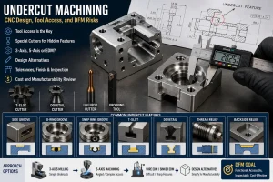
Some Parts Need Both Milling and Turning
Many CNC components are not purely milled or purely turned.
A round part may still need:
- Milled flats
- Cross holes
- Keyways
- Side slots
- Radial ports
- Off-center holes
- Engraved marks
- Mounting features
A milled part may still need:
- Precision bores
- Turned inserts
- Round mating features
- Bearing seats
- Bushings
- Cylindrical pins
- Threaded standoffs
When both processes are required, the key question becomes:
Which features should be machined first, and which datum should control the next setup?
For mixed-geometry parts, the process route should also review whether secondary milling can be reduced or combined with turning-related operations. When live tooling, mill-turn capability, or a suitable combined setup is available, radial holes, flats, slots, and selected side features may be machined without moving the part to a completely separate setup.
This can reduce repositioning risk, fixture cost, and accumulated error between turned diameters and milled features. It is especially useful when side holes, flats, or milled details must remain aligned with a central bore, shaft diameter, or turned datum.
However, a combined route is not automatically the best choice for every part.
The decision still depends on:
- Feature geometry
- Datum relationship
- Quantity
- Machine access
- Tool clearance
- Tolerance requirements
- Inspection method
- Cost target
For simple parts, a separate turning or milling route may still be more efficient. For parts where the datum relationship is critical, reducing unnecessary re-clamping can be more important than choosing the lowest hourly machine rate.
A poor process sequence may create:
- Accumulated tolerance error
- Datum mismatch
- Run-out
- Position error
- Burrs at intersecting features
- Surface marks during re-clamping
- Inspection disputes
This is where process planning matters more than the process name.
The Datum Strategy Can Change the Best Process
A feature may look easy in CAD but become difficult after datum requirements are considered.
For example, a cylindrical part with a side hole may be simple if the side hole only needs clearance. But if that side hole must hold a tight position relative to a turned bore, the machining route and inspection plan become more important.
The process must consider:
- Which surface is the primary datum
- Which diameter controls assembly
- Which face controls location
- Whether the part must be re-clamped
- Whether the critical features can be machined in one setup
- Whether turning, milling, or mill-turn machining reduces accumulated error
- Whether CMM inspection or functional gauges are required
A milling process may control a hole pattern better.
A turning process may control concentric features better.
A combined route may be required when both relationships matter.
For datum-related tolerances, post-finish dimensions, fitted holes, and GD&T planning, review our CNC machining tolerances guide.
Material Behavior Can Influence Process Choice
The same geometry may behave differently depending on material.
Aluminum Alloys
Aluminum is generally efficient to machine, but thin walls, large pockets, and broad flat surfaces may move after material removal.
For aluminum housings, brackets, and enclosures, milling strategy should review:
- Wall thickness
- Clamping force
- Roughing and finishing sequence
- Tool reach
- Burr control
- Flatness
- Surface finish
- Anodizing allowance
Stainless Steel
Stainless steel may increase cutting heat, tool wear, work-hardening risk, and burr formation.
For stainless turned or milled parts, review:
- Tool condition
- Chip control
- Coolant delivery
- Hole depth
- Thread quality
- Burr removal
- Passivation requirements
- Surface inspection
Copper and Brass
Copper and brass are often selected for conductivity, appearance, or application-specific mechanical needs.
Copper may create burrs, smearing, handling marks, and oxidation concerns.
Brass may be easier to machine depending on grade, but material selection must still match the application.
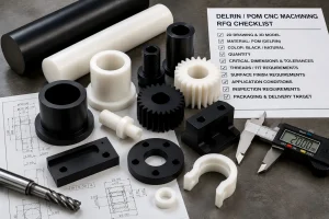
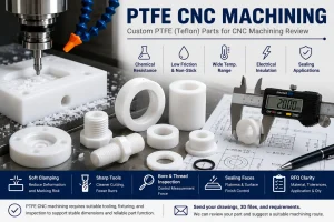
Engineering Plastics
Engineering plastics may create different risks from metals.
The process should review:
- Clamping deformation
- Thermal movement
- Burrs or fuzzy edges
- Dimensional recovery after machining
- Inspection timing
- Surface quality
- Moisture sensitivity for selected grades
For a broader material comparison, review our CNC machining materials guide.
Tolerance and Surface Finish Are Not Only Process Labels
A customer may ask:
Is milling more accurate than turning?
That is not the best question.
A more useful question is:
Which process controls the functional features with fewer setups, better datum control, and more reliable inspection?
Turning may control roundness, diameter, and concentric features effectively.
Milling may control flatness, hole patterns, pockets, and multi-face geometry more effectively.
The tolerance result depends on:
- Machine capability
- Tooling
- Fixture design
- Material behavior
- Setup sequence
- Feature size
- Tool reach
- Heat control
- Surface treatment
- Inspection method
Surface finish also depends on the operation.
A turned surface may show circular tool marks.
A milled surface may show cutter paths.
A polished surface may look better but change edge definition or functional surfaces.
A bead-blasted or anodized part may look more uniform but still require dimensional planning.
When post-processing is required, review our CNC surface finishes guide.
Cost Is Usually Driven by Setup and Feature Risk
The cheapest route is not always the process with the lower hourly machine rate.
Cost often comes from:
- Number of setups
- Fixture requirements
- Tool changes
- Long-reach tools
- Deep holes
- Tight tolerances
- Burr removal
- Surface finishing
- Inspection reports
- Scrap risk
- Rework risk
- Packaging requirements
For turned round parts, raw-material format can also change the cost structure. If the geometry allows continuous bar stock and automated feeding, turning may reduce manual handling, saw-cut preparation, and repeated loading time compared with machining separate prismatic billets one by one.
This is one reason simple round components, bushings, sleeves, spacers, and threaded inserts can often be more efficient on turning-based routes when the quantity and geometry support it.
But this advantage depends on:
- Part diameter
- Part length
- Material form
- Batch quantity
- Tolerance requirement
- Cutoff condition
- Secondary features
- Surface-finish requirement
- Inspection plan
A round part with many milled side features may lose the advantage if it requires multiple secondary setups.
A turned part with one secondary milled flat may be efficient.
A turned part with many side holes, slots, pockets, and angular features may require multiple setups or a different process route.
A milled housing with one simple bore may remain a milling part.
A milled housing with a tight bearing seat and round sealing surface may require additional boring, turning-related review, or controlled inspection.
Before quotation, the process route should be reviewed against the features that carry risk, not only the shape of the raw material.
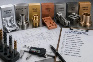
RFQ Checklist for CNC Milling vs CNC Turning
Before requesting a quotation, prepare:
- 2D drawing
- 3D CAD file
- Material grade
- Expected quantity
- Critical dimensions
- General tolerance note
- GD&T callouts
- Thread requirements
- Hole depths
- Fitted bores
- Bearing locations
- Mating faces
- Sealing surfaces
- Flatness requirements
- Run-out requirements
- Surface-finish requirements
- Heat-treatment requirements
- Inspection-report requirements
- Packaging requirements
- Assembly function when available
When the process is not yet clear, identify the most important functional features.
Examples include:
- Shaft diameter
- Precision bore
- Flat mounting face
- Hole pattern
- Side hole location
- Sealing face
- Threaded interface
- Bearing seat
- Cosmetic surface
- Assembly datum
This helps the machining team decide whether milling, turning, or a combined route is more appropriate.
Buyer Questions About CNC Milling vs CNC Turning
Can CNC milling make round parts?
Yes, CNC milling can machine round features, circular pockets, and bores.
However, if the part is mainly controlled by round external and internal diameters, CNC turning may be more efficient and more suitable.
The best route depends on the feature, tolerance, quantity, material, and datum relationship.
Can CNC turning make holes and slots?
CNC turning can machine center holes, bores, grooves, and threads.
Cross holes, flats, side slots, and off-axis features may require secondary milling, live tooling, or another setup.
The drawing should identify which features are functional and how they relate to the main datum.
Is mill-turn machining always better?
No.
A mill-turn route can reduce setup changes for certain parts, but it is not automatically the best option for every project.
For simple round parts, turning may be more efficient.
For prismatic housings, milling may be more suitable.
For mixed-geometry parts, the decision depends on tolerance relationships, feature access, quantity, and inspection requirements.
How do I know which process to request in my RFQ?
You do not need to choose the process perfectly before sending the RFQ.
Send the 2D drawing, 3D CAD file, material grade, quantity, tolerance requirements, surface finish, and application notes.
The machining route can then be reviewed based on geometry, functional features, cost drivers, and inspection risk.
Upload Your Drawing for Process Review
Send your 2D drawing, 3D CAD file, material grade, expected quantity, tolerance notes, surface-finish requirements, inspection needs, and delivery target.
Our team will review whether CNC milling, CNC turning, or a combined machining route is more suitable for your custom part.
CTA Button: Upload Your Drawing
About Rapid Efficient
Rapid Efficient supports custom CNC machining projects for prototypes, low-volume parts, and production requirements.
With 18 years of high-precision CNC machining experience, our team reviews material behavior, machining strategy, tolerance risks, post-processing requirements, inspection methods, packaging conditions, and delivery schedules before quotation.
Our available capabilities include 4-axis, 5-axis, and multi-axis CNC machining, together with inspection equipment such as CMM, projectors, and spectrometers.
Depending on the actual part and project requirements, machining accuracy down to 0.01 mm and inspection accuracy down to 0.001 mm are available.
Rapid Efficient has obtained ISO 9001 and ISO 14001 certification.
We support projects across medical devices, communications equipment, optical components, drones, intelligent robotics, automotive applications, office automation, and other custom manufacturing requirements.