304 stainless steel is not difficult to machine simply because it starts as a hard material.
The real problem begins when the cutting edge rubs instead of shearing cleanly.
Once the surface begins to work-harden, the next tool pass is no longer cutting the same material condition. The tool meets a harder layer, heat accumulates near the cutting zone, chips become more difficult to control, and the risk of built-up edge, burrs, tool wear, surface marks, and dimensional drift increases.
A cautious-looking machining strategy can make the problem worse.
If the feed becomes too light, the tool dwells too long, or a worn cutting edge is allowed to continue rubbing against the workpiece, the process may create the hardened surface that the next pass must fight through.
For custom CNC parts, the correct question is not:
Can 304 stainless steel be machined?
The more useful question is:
Which features are likely to trigger work-hardening, chip-control problems, surface damage, or inspection risk before the part reaches final assembly?
Why 304 Becomes Difficult After the First Bad Pass
304 is an austenitic stainless steel commonly selected for corrosion resistance, clean appearance, formability, and general industrial use.
Its machining behavior is different from that of carbon steel, free-machining stainless steel, aluminum, and brass.
The key risks are connected:
- The material can work-harden during cutting.
- The chips are often tough, long, and difficult to break.
- Adhesion may create built-up edge on the tool.
- Cutting heat can concentrate around the cutting zone.
- A worn edge may rub instead of cutting cleanly.
- The hardened surface may accelerate additional tool wear.
- Burrs and surface marks can become more difficult to remove without affecting dimensions.
304 cannot be hardened by conventional heat treatment in the same way as a hardenable steel grade.
However, cold deformation can increase its strength and hardness.
That is why a machining process may become unstable even when the raw material initially appears manageable.
The first poor pass is not always an isolated defect.
It may change the surface condition for every pass that follows.
Shop-Floor Failure Map for 304 Stainless Steel
| Symptom on the Part or Tool | Likely Process Conflict | What to Review Before the Next Part | Inspection Impact |
|---|---|---|---|
| Built-up edge or material stuck to the tool | Adhesion, cutting-edge rubbing, poor chip evacuation, unstable cutting conditions | Tool condition, edge geometry, cutting engagement, coolant delivery, chip form | Review surface marks, dimensional consistency, and edge condition |
| Long stringy chips wrapping around the tool or workpiece | Tough chip formation, unsuitable chip-breaking strategy, insufficient evacuation | Tool geometry, feed strategy, coolant flow, hole depth, tool access | Check scratches, damaged edges, hole quality, and operator-handling risk |
| Rapid flank wear, edge chipping, or inconsistent tool life | Work-hardened surface layer, interrupted cutting, excessive heat, unstable setup | Tool rigidity, tool overhang, cutting-depth consistency, fixture stability, replacement interval | Compare dimensions between early and late parts in the batch |
| Rolled burrs around holes, slots, and edges | Ductile material behavior, worn tool, poor exit condition, insufficient deburring plan | Tool sharpness, feature orientation, exit edge, deburring access, cosmetic requirement | Check whether burr removal changes hole size, edge geometry, or surface finish |
| Poor hole finish, taper, or inconsistent diameter | Chip jamming, run-out, tool wear, insufficient coolant, excessive depth-to-diameter ratio | Hole depth, through-hole or blind-hole condition, internal coolant, drill geometry, gauge plan | Use the correct gauge or measurement route for the functional requirement |
| Rough threads or failed thread-gauge inspection | Work-hardening, burrs, chip retention, blind-hole contamination, tool wear | Pilot-hole condition, thread depth, chip removal, tap condition, inspection method | Confirm thread-gauge acceptance and post-cleaning verification |
| Thin-wall movement after unclamping | Clamping force, heat, uneven material removal, insufficient finishing allowance | Fixture strategy, roughing and finishing stages, wall thickness, inspection timing | Inspect the part after unclamping rather than only while constrained |
| Surface marks remaining after machining | Worn edge, chip recutting, excessive rubbing, uncontrolled polishing | Tool condition, chip evacuation, cosmetic requirement, polishing allowance | Separate cosmetic acceptance from dimensional acceptance |
| Residue or corrosion concern after post-processing | Incomplete deburring, insufficient cleaning, blind holes, internal threads, trapped liquid | Cleaning route, rinsing, drying, passivation requirement, packaging | Include visual inspection and post-finish verification where required |
This table is a diagnostic tool, not a universal process recipe.
The final machining route should still be reviewed against the drawing, material certificate, feature geometry, production quantity, surface requirement, and inspection plan.
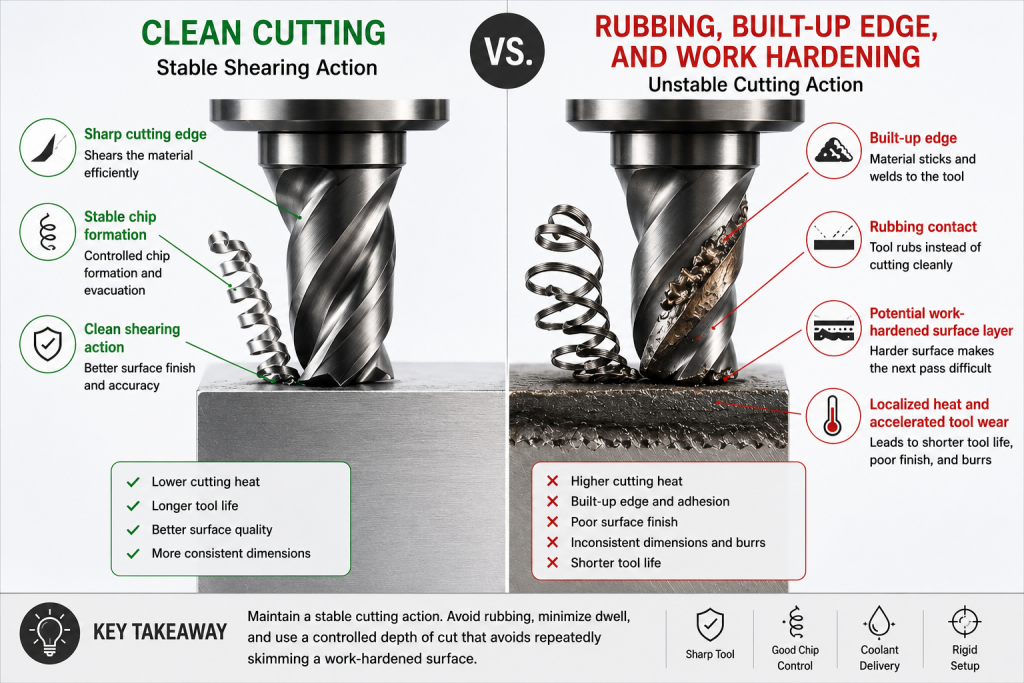
The Tool Must Keep Cutting, Not Rubbing
The most important rule when machining 304 stainless steel is simple:
Maintain a stable cutting action and avoid creating a polished, work-hardened surface in front of the next tool pass.
The exact tool grade, coating, cutting speed, feed rate, and depth of cut depend on the machine, operation, tool diameter, rigidity, stock form, feature geometry, coolant route, and batch size.
There is no single parameter table that can be copied safely into every 304 stainless-steel project.
However, the process strategy should normally review the following points.
Use a Sharp Cutting Edge
Monitor tool wear before rubbing, adhesion, and surface damage begin.
A worn cutting edge increases rubbing, heat, adhesion, and surface damage.
Tool condition should be monitored before the cutting edge begins to create a hardened layer that damages the next operation.
This matters especially before:
- Finishing passes
- Small holes
- Internal threads
- Thin-wall features
- Cosmetic faces
- Tight-fit bores
- Sealing surfaces
Use a Stable Toolpath
Keep the cutting action continuous and predictable rather than allowing repeated rubbing or unstable re-entry.
Repeated rubbing passes, unnecessary dwell time, unstable entry, and inconsistent engagement can make work-hardening more difficult to control.
The toolpath should protect:
- Consistent cutting engagement
- Stable chip formation
- Predictable heat generation
- Sufficient chip evacuation
- Repeatable dimensional control
Cut Below the Hardened Surface
Do not let a finishing pass merely skim across a work-hardened surface.
A light pass is not automatically a safe pass.
If the tool only skims the workpiece, it may rub against the hardened surface instead of removing it effectively.
The finishing plan should account for the previous operation and leave a controlled amount of material for a stable final cut.
Keep the Setup Rigid
Control tool overhang, clamping, and support before chasing tighter dimensions.
Tool overhang, fixture movement, chatter, and poor support may reduce surface quality and accelerate tool wear.
Rigidity matters when the component includes:
- Deep pockets
- Long-reach tools
- Thin walls
- Narrow slots
- Small-diameter cutters
- Interrupted cuts
- Multi-face machining
- Tight GD&T requirements
Holes and Threads Are Often the First Features to Fail
A drawing may appear simple until it includes a deep blind hole, a narrow fitted bore, or an internal thread near the bottom of a pocket.
304 stainless steel makes these features more sensitive because chip evacuation, heat, tool condition, and work-hardening interact.
Hole Depth Must Be Included in the RFQ
A Ø6 mm hole with a depth of 8 mm is not the same manufacturing task as a Ø6 mm hole with a depth of 35 mm.
As the depth-to-diameter ratio increases, the process must review:
- Chip evacuation
- Internal coolant
- Drill run-out
- Tool rigidity
- Cutting heat
- Tool wear
- Entry and exit conditions
- Inspection access
- Blind-hole residue
- Bottom clearance for threads
For deeper holes, internal coolant and chip control become increasingly important.
A hole deeper than 3 × D should be treated as an early review trigger rather than an automatic rejection point.
Fitted Holes Need a Process and Inspection Plan
A precision hole should not be treated like a standard clearance hole.
Depending on the drawing and tolerance, the machining route may require:
- Controlled interpolation
- Precision boring
- Reaming
- A dedicated tool
- Trial parts
- In-process checks
- Pin-gauge inspection
- Plug-gauge inspection
- Bore-gauge verification
- CMM inspection
- Functional assembly checks
The correct route depends on the feature.
For fitted bores, H7 holes, GD&T relationships, and post-finish dimensions, review our CNC machining tolerances guide.
Threads Need Space for Chips and Inspection
Internal threads create additional risk when the feature is deep, blind, small, or difficult to clean.
Before production, confirm:
- Thread standard
- Thread size
- Thread depth
- Blind-hole depth
- Bottom clearance
- Pilot-hole condition
- Chip-removal route
- Deburring method
- Thread-gauge requirement
- Cleaning and drying requirements
- Passivation requirement when applicable
A thread that looks acceptable under visual inspection may still fail a gauge or trap residue after finishing.
Do Not Silently Replace 304 with a More Machinable Grade
When productivity becomes difficult, the solution is not always to continue forcing the same process.
The material grade should be reviewed before production.
304 is often selected because the application needs a practical balance of corrosion resistance, availability, appearance, weldability, and cost.
Other stainless grades may machine differently.
For example, sulfur additions can improve machinability and chip breaking in selected grades, but the corrosion-resistance trade-off must be reviewed against the application.
A free-machining grade should not be substituted silently just because it cuts faster.
The RFQ should identify:
- Exact stainless-steel grade
- Material-certificate requirement
- Corrosion environment
- Food-contact, medical, or cleaning requirement when relevant
- Welding requirement
- Surface-finish requirement
- Passivation requirement
- Dimensional and cosmetic acceptance criteria
For a broader comparison of stainless steel, aluminum, copper alloys, and engineering plastics, review our CNC machining materials guide.
Thin Walls, Flatness, and Cosmetic Faces Need Different Controls
Not every 304 stainless-steel part fails because of a broken tool.
Some parts become expensive because they look simple but include thin walls, large pockets, narrow ribs, broad cosmetic surfaces, or tight flatness requirements.
Thin-Wall Features
Thin-wall movement may come from:
- Clamping force
- Cutting heat
- Uneven stock removal
- Tool pressure
- Residual stress
- Insufficient roughing and finishing stages
- Inspection while the part is still constrained
A stable route may require:
- Controlled clamping force
- Symmetrical material removal
- Multiple machining stages
- Finishing allowance
- Intermediate inspection
- Unclamped inspection
- Functional assembly review
Cosmetic Surfaces
A cosmetic stainless-steel surface is not the same as a dimensional surface.
A part may meet its dimensional requirements and still be rejected because of:
- Tool marks
- Scratches
- Burrs
- Polishing variation
- Handling marks
- Inconsistent grain direction
- Residue
- Packaging damage
The drawing should separate:
- Functional surfaces
- Cosmetic faces
- Sealing surfaces
- Mating faces
- Areas permitted to show machining marks
- Areas requiring polishing or brushing
- Areas requiring passivation
- Areas requiring protection during packaging
Sealing and Mating Surfaces
A polishing step can improve appearance but still damage fit when it rounds edges or removes too much material from a functional surface.
Before polishing or brushing, confirm whether the surface controls:
- Flatness
- Seal contact
- Bearing alignment
- Assembly location
- Sliding behavior
- Cosmetic appearance only
Passivation Is Not a Repair Process
Passivation may be specified after machining, deburring, and cleaning when the part requires corrosion-resistant surface conditions.
However, passivation does not repair:
- Rolled burrs
- Deep tool marks
- Incorrect dimensions
- Failed threads
- Scratches
- Embedded chips
- Poor polishing
- Trapped residue
- Packaging damage
The machining and finishing route should be planned in the correct sequence:
- Machine the part.
- Deburr the required edges.
- Inspect critical dimensions and threads.
- Clean the component.
- Apply the specified passivation route when required.
- Rinse and dry the part correctly.
- Perform post-finish inspection when required.
- Protect the component during packaging.
Avoid Cross-Contamination from Carbon Steel
Stainless-steel parts should not be exposed to abrasive media, polishing tools, wire brushes, or tumbling media that may have previously contacted carbon-steel parts.
Foreign iron contamination can create rust staining or corrosion concerns even when the stainless-steel grade itself is correct.
Where deburring, tumbling, bead blasting, grinding, or polishing is required, review whether the tools and media are reserved for stainless-steel processing.
Passivation may help remove exogenous iron from the surface, but it should not be treated as a substitute for proper segregation, precleaning, rinsing, drying, and contamination control.
For projects with corrosion-resistance requirements, confirm:
- Whether dedicated stainless-steel tools or media are required
- Whether tumbling or blasting media has contacted carbon steel
- Whether blind holes and internal threads can be rinsed effectively
- Whether free-iron testing is required
- Whether packaging conditions may expose the part to moisture during shipment
Blind holes and internal threads deserve particular attention because trapped liquid and insufficient rinsing may create problems that are not visible from the external surface.
For a deeper process review, read our guide to stainless steel passivation for CNC parts.
Inspection Before Delivery
A 304 stainless-steel component should not be accepted only because the outside dimensions appear correct.
The inspection route should follow the functional risks in the drawing.
Depending on the part, the final plan may include:
- Outer dimensions
- Precision bores
- Hole depth
- Hole position
- Flatness
- Parallelism
- Perpendicularity
- True position
- Run-out
- Thread-gauge checks
- Burr inspection
- Cosmetic-surface review
- Surface-roughness checks
- Post-passivation inspection
- Packaging verification
- Material certificates
- Dimensional reports
- CMM reports when required
Not every feature requires CMM inspection.
For example:
- A thread gauge may be the correct tool for a threaded feature.
- A pin gauge or plug gauge may be more direct for a fitted hole.
- A micrometer may be appropriate for selected shaft dimensions.
- A CMM may be useful for hole patterns, datum relationships, profiles, and multi-face GD&T requirements.
The inspection method should match the functional requirement rather than the perceived sophistication of the equipment.
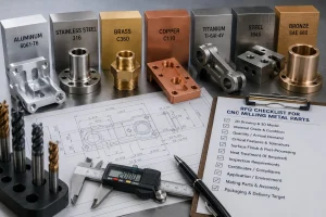
Information to Include in a 304 Stainless-Steel RFQ
Before requesting a quotation, prepare:
- 2D drawing
- 3D CAD file
- Exact material grade: 304, 304L, or another specified grade
- Material-certificate requirement
- Stock-form requirement when relevant
- Expected quantity
- Critical tolerances
- General-tolerance note
- Thin-wall areas
- Deep holes
- Blind holes
- Threads
- Hole depths
- Fitted bores
- Bearing locations
- Sealing surfaces
- Mating surfaces
- GD&T callouts
- Surface-roughness requirements
- Cosmetic surfaces
- Polishing or brushing requirements
- Passivation requirement
- Inspection-report requirements
- Sampling or 100% inspection expectations
- Packaging requirements
- Application environment
- Target delivery schedule
When the drawing is still under development, identify the failure mode that must be avoided.
Examples include:
- Thread failure
- Burrs around small holes
- Flatness drift
- Cosmetic scratches
- Poor sealing
- Assembly interference
- Corrosion concern
- Residue in blind holes
- Surface marks on visible faces
This helps the machining route, inspection plan, and quotation reflect the actual project risk.
Buyer Questions About Machining 304 Stainless Steel
How do I prevent work-hardening during a tool change or programmed pause?
A tool change, in-process measurement step, or programmed pause should not leave the cutting edge rubbing against the workpiece surface.
Before the spindle pauses or the tool is changed, the program should include a controlled retract path that moves the cutting edge away from the material.
This matters because rubbing may leave a locally work-hardened surface for the next tool pass.
When the replacement tool re-enters the feature, it may meet a more difficult surface condition than expected.
The process plan should review:
- Retract path before a pause
- Re-entry position
- Tool engagement after restart
- Chip clearance
- Coolant delivery
- Tool condition
- Whether an in-process inspection step changes the cutting sequence
The objective is simple:
Pause away from the cutting surface, then re-enter with a stable cutting action.
Can 304 stainless steel be hardened by heat treatment?
304 stainless steel is not hardened by conventional heat treatment in the same way as hardenable steel grades.
However, cold deformation can increase its strength and hardness.
This is one reason machining strategy matters: rubbing and repeated deformation can create a harder surface layer in front of the next cutting pass.
Is 303 stainless steel easier to machine than 304?
303 is generally selected when improved machinability is important and the application allows the trade-off.
The correct choice still depends on corrosion resistance, cleaning requirements, surface finish, welding, inspection, and operating environment.
Do not substitute the grade without confirming the drawing and application.
Should every 304 stainless-steel part be passivated?
No.
Passivation depends on the drawing, corrosion environment, cleanliness requirement, application, and customer specification.
When passivation is required, deburring, cleaning, rinsing, drying, internal features, contamination control, and post-finish inspection should be reviewed together.
Upload Your Drawing for 304 Stainless-Steel Machining Review
Send your 2D drawing, 3D CAD file, material grade, quantity, tolerance notes, hole and thread details, surface requirements, passivation needs, inspection requirements, and delivery target.
Our team will review the machining route, work-hardening risks, chip-control requirements, fixture strategy, deburring route, inspection plan, finishing requirements, packaging conditions, and delivery schedule before quotation.
CTA Button: Upload Your Drawing
About Rapid Efficient
Rapid Efficient supports custom CNC machining projects for prototypes, low-volume parts, and production requirements.
With 18 years of high-precision CNC machining experience, our team reviews material behavior, machining strategy, tolerance risks, post-processing requirements, inspection methods, packaging conditions, and delivery schedules before quotation.
Our available capabilities include 4-axis, 5-axis, and multi-axis CNC machining, together with inspection equipment such as CMM, projectors, and spectrometers.
Depending on the actual part and project requirements, machining accuracy down to 0.01 mm and inspection accuracy down to 0.001 mm are available.
Rapid Efficient has obtained ISO 9001 and ISO 14001 certification.
We support projects across medical devices, communications equipment, optical components, drones, intelligent robotics, automotive applications, office automation, and other custom manufacturing requirements.