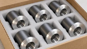
An existing hole can be within size at the entrance and still fail in assembly. It may taper toward the bottom, open into a bell mouth, have an axis that is mislocated or tilted relative to the required datum, carry chatter marks, or change after the fixture is released.
Boring machining is used when a drilled, cast, forged, or previously machined hole must become a controlled functional bore. The operation enlarges the hole with a single-point cutting tool or an adjustable boring head. Depending on the setup, it can improve diameter, straightness, alignment, roundness, shoulder geometry, and surface quality.
It is not a correction for every hole problem. The starting hole must provide tool access and sufficient cleanup stock. The boring bar must be rigid enough for the required depth. The drawing must also distinguish bore size from form, position, orientation, and finish.
Quick answer: Boring is appropriate when an existing hole needs more control than drilling can provide and when the process must influence the bore axis or its relationship to another machined feature. Reaming may be more efficient for a straight hole with a small, uniform allowance. Honing or internal grinding may be required when final form, finish, hardness, or stock allowance exceeds a practical boring route.
Boring Does Not Create the First Hole
Boring begins with an opening. That opening may come from drilling, casting, forging, coring, laser cutting, or a previous machining operation. The cutting edge then travels along the internal surface and removes material to enlarge or reshape it.
On a lathe or vertical turning machine, the workpiece rotates while the boring bar feeds through the hole. On many machining centers and horizontal boring mills, the boring tool rotates while the workpiece remains fixed. Both routes can produce straight bores, tapered bores, stepped diameters, counterbores, and internal shoulders when tool access allows.
In CNC boring, programmed motion and tool offsets control the commanded path, but the finished geometry still depends on the spindle, holder, bar, insert, workholding, stock distribution, and part temperature. Rough boring removes the main allowance. Fine boring uses a more controlled finishing cut and an adjustable tool when the feature and production plan justify it.
The starting hole still matters. If it is too small, the bar may lack body clearance or chip space. If it is badly offset, part of the wall may not clean up at the finished diameter. If the stock is highly uneven, the cutting load can vary around the bore and deflect the tool.
For this reason, a finished diameter alone does not define a boring operation. The supplier also needs the pre-hole condition, depth, material, datum relationship, bottom geometry, and expected stock allowance.
Choose Boring When the Existing Hole Is the Problem
Boring becomes valuable when the bore must do more than accept a loose fastener. Typical examples include a bearing seat, a precision sleeve, an internal locating diameter, a sealing bore, a hydraulic housing, or a stepped bore that must relate to a face or outside diameter.
| Starting condition or requirement | Why boring may help | Main risk to review | Useful verification |
|---|---|---|---|
| Drilled hole needs a controlled fit | An adjustable cutting edge can bring the bore toward the required diameter | Tool deflection, finish allowance, thermal drift | Bore gauge or internal micrometer at multiple depths |
| Cast hole has uneven stock | Rough boring can establish a machined reference before finishing | Incomplete cleanup, interrupted load, casting movement | Visual cleanup check plus diameter and location measurement |
| Bearing bore must relate to a mounting face | A machining-center setup can establish the bore from defined datums | Fixture alignment, spindle condition, setup movement | CMM or fixture-based location and orientation check |
| Turned bore must run with an outside diameter | Boring the ID and turning the OD in one setup can protect the shared axis | Chuck distortion, tool reach, part reversal | Bore size plus runout or coaxial relationship as specified |
| Stepped bore needs controlled shoulders | A boring tool can generate multiple internal diameters and axial faces | Tool access, corner radius, shoulder depth, chip trapping | Diameter, depth, shoulder location, and radius inspection |
| Deep or small bore needs very fine finish | Boring may establish size before another finishing process | Slender tooling, vibration, inspection access | Review honing, grinding, or another specialist process before release |
Boring is usually unnecessary for a generous clearance hole that drilling already produces economically. It is also a poor rescue plan when the starting hole does not leave enough material for complete cleanup, or when the required bore is too small for a sufficiently rigid bar.
Drilling, Boring, Reaming, and Honing Correct Different Problems
These processes may appear in the same routing, but they do not perform the same correction.
| Process | What it starts with | Primary job | What it can control well | Important limitation |
|---|---|---|---|---|
| Drilling | Solid stock or a pilot hole | Create the initial hole | Hole creation, depth, general diameter | Drill runout, walking, deflection, and chip flow may limit final size and axis control |
| Boring | Existing hole | Enlarge and establish a more controlled internal geometry | Adjustable diameter, internal shoulders, taper, and axis relationship to the setup | A slender bar can deflect or chatter; the process cannot add material to an oversized hole |
| Reaming | Consistent pre-hole with a small allowance | Size and finish a straight bore efficiently | Repeat diameter and surface quality for a suitable hole | A reamer tends to follow the existing path and is not a dependable correction for major location error or uneven stock |
| Honing | Machined bore near final size | Refine surface texture and small form or size errors | Fine finish, crosshatch, and selected bore-form correction | It is not intended to remove a large offset or establish a new bore location |
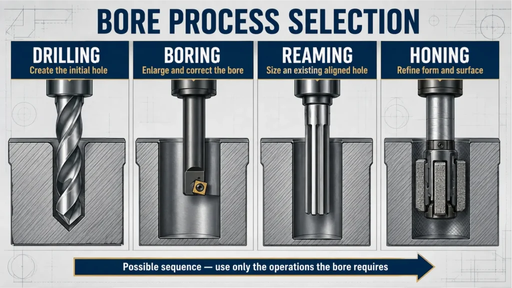
A common route is drill, rough bore, finish bore, and then inspect. Another route may use drilling followed by reaming. Bores requiring a specific surface texture or more demanding form control may continue to honing or internal grinding.
The correct sequence depends on what is wrong with the starting hole and what the finished bore must control. “Tight tolerance” by itself is not enough information to choose the route.
Lathe Boring and Machining-Center Boring Protect Different Relationships
Boring on a lathe is often appropriate for sleeves, bushings, rings, flanges, adapters, and other rotational parts. If the bore, outside diameter, and reference face are machined without releasing the part, the setup can help protect their shared rotational relationship.
The clamping method still matters. Thin rings and sleeves may change shape under jaw pressure and recover after removal.
Projects centered on rotational geometry can be reviewed through our CNC turning services, where bore depth, runout, wall thickness, grooves, threads, and inspection requirements are considered together.
Machining-center boring is often used for housings, plates, brackets, manifolds, and bore patterns. Here the rotating tool is positioned from machine coordinates and part datums. The key risk may be the relationship between the bore axis, mounting plane, bolt pattern, or another bore rather than its diameter alone.
For prismatic parts, CNC milling services can combine datum-face machining, drilling, boring, and related features in a coordinated setup when the geometry is suitable.
A dedicated horizontal boring mill, line-boring arrangement, or deep-hole process may be needed for large structures or unusual reach. Those projects should be reviewed as specialized work before quotation rather than assumed from the word “boring.”
The Boring Bar Often Sets the Limit
Internal machining places the cutting edge at the end of a cantilevered bar. As overhang increases, the bar becomes more sensitive to cutting force.
The result can be taper, diameter variation, chatter, insert damage, or a finish that changes from the mouth to the bottom of the bore.
The first stability decisions are mechanical:
- Use the largest practical bar diameter that still provides body and chip clearance.
- Keep unsupported projection as short as the feature permits.
- Support the holder close to the cutting zone.
- Confirm that the bar, insert screw, insert seat, and holder are clean and undamaged.
- Select insert geometry and edge preparation for the material and finishing allowance.
- Review whether a damped bar is justified for a longer reach.
- Direct coolant and chips out of the bore without forcing chips back across the finished wall.
A larger insert nose radius may support finish and edge strength under stable conditions, but it can also increase radial cutting force.
A smaller radius or more positive geometry may reduce force for a slender bar or thin wall, although feed, insert strength, and required finish must be reviewed together.
Tool clearance is equally important. A bar that barely enters the starting hole may rub below the cutting edge or trap chips. The largest practical bar is useful only when there is still room for the body, coolant, and chip evacuation.
For internal turning, an unsupported overhang around four times the bar diameter is a practical trigger to review a conventional steel bar rather than a universal failure limit.
Depending on bore diameter, cutting load, holder condition, material, and finish requirement, a carbide bar may provide greater static stiffness, while a damped bar may help control vibration. The actual choice should follow the tooling supplier’s data and the complete setup.
Why a Light Finishing Cut Can Still Produce Taper
Buyers sometimes assume that the last pass can simply remove a few micrometers and correct the bore.
In practice, an extremely light cut may rub instead of forming a stable chip. A worn or heavily honed cutting edge can increase this risk.
The finish allowance should be large enough for the selected edge to cut consistently, but small enough to limit force and heat. Uniform stock is important.
If one side of the pre-hole carries more material, the tool load changes as it rotates or as the workpiece rotates, which may move the cutting edge away from the programmed path.
Several workshop details matter:
- Roughing should leave a controlled allowance along the full bore depth.
- A semi-finishing pass may reveal whether taper or stock variation remains before the final cut.
- Entry and exit moves should avoid dwelling on a functional diameter.
- For machining-center fine boring, some controls can stop and orient the spindle, then shift the insert clear of the bore before rapid retraction. On a lathe, a programmed radial clearance move may serve the same purpose before axial withdrawal. The cycle, shift direction, and available clearance should be verified for the actual machine and tool orientation to avoid an axial or helical witness mark.
- A repeated spring pass can remove material left by elastic deflection, but it may also rub or change size. It should not be treated as an automatic cure.
- Offset changes should follow a stable measurement pattern. A diameter offset cannot correct a changing taper, lobing, or datum error.
- Bore temperature and part temperature can affect the measured size, especially during repeated finishing passes.
If the entrance is correct but the far end is not, changing one tool offset may sacrifice the good section without correcting the underlying stiffness or thermal problem.
Blind Ends, Cross Holes, and Thin Walls Change the Plan
A through bore provides a chip exit and allows the tool to pass beyond the functional length when the setup permits.
A blind bore traps chips near the bottom and requires controlled clearance between the insert, bar, internal shoulder, and bottom geometry.
The drawing should show whether the bottom is allowed to retain a drill point, whether a flat bottom is functional, and what corner radius is acceptable. A sharp internal corner cannot be produced by a normal insert with a finite nose radius.
Cross holes create an interrupted cut. Each interruption changes the load on the cutting edge and can create an internal burr where the features meet.
That burr may be difficult to see and may interfere with flow, seals, assembly, or cleaning. Tool direction, cutting sequence, edge condition, and access for deburring should be reviewed before machining.
Thin-wall bores introduce a different problem. Clamping force can temporarily distort the part, while the cutting force and heat can move the wall during the pass.
The bore may measure differently after the chuck or fixture is released. For this geometry, final inspection should represent the agreed free-state or restrained condition.
Coatings and heat treatment also affect routing. If a plated, anodized, coated, or heat-treated bore has a final fit requirement, the drawing should state whether the dimension applies before or after processing and whether masking or finish allowance is required.
Read the Bore Error Pattern Before Changing an Offset
The same nominal diameter can hide several failure modes. Measuring at one depth and one orientation may miss the problem.
| Observed pattern | Possible process causes | Why a simple offset may fail | Better confirmation method |
|---|---|---|---|
| Bore becomes smaller or larger with depth | Bar deflection, thermal change, tool alignment, uneven stock, part support | One offset moves the full diameter but does not remove the taper | Measure at several depths and directions; review setup and bar projection |
| Entrance is wider than the remaining bore | Entry instability, dwell, edge engagement change, local relief or setup movement | Correcting the average diameter can make the stable section incorrect | Compare mouth measurement with deeper sections and inspect the entry path |
| Middle section differs from both ends | Workpiece flex, clamping distortion, heat, varying wall thickness | The error is not a constant diameter shift | Map the bore along its depth after fixture release |
| Different readings appear at different angular directions | Ovality, lobing, chuck distortion, interrupted stiffness | One two-point reading may not represent the full form | Rotate the measurement direction; use suitable roundness or CMM analysis when required |
| Regular waves or audible chatter appear | Excessive bar reach, weak holder, unstable cutting parameters, insert geometry, interrupted cut | Diameter compensation does not remove vibration | Inspect the surface pattern, reduce the instability source, and recheck size and finish |
| Diameter drifts across a batch | Insert wear, heat growth, chip buildup, offset handling, gauge setup | A one-time correction may only move the drift | Trend measurements from a controlled gauge setup and review tool life |
| Bore size passes but assembly alignment fails | Position, perpendicularity, coaxial relation, runout, or datum interpretation | Bore diameter is not the failed characteristic | Inspect the bore axis relative to the functional datum or mating feature |
| Internal intersection remains sharp or burred | Cross-hole sequence, rolled burr, inaccessible edge, chip recutting | Diameter inspection does not detect the obstruction | Borescope, visual access, probe, airflow, or functional check depending on the feature |
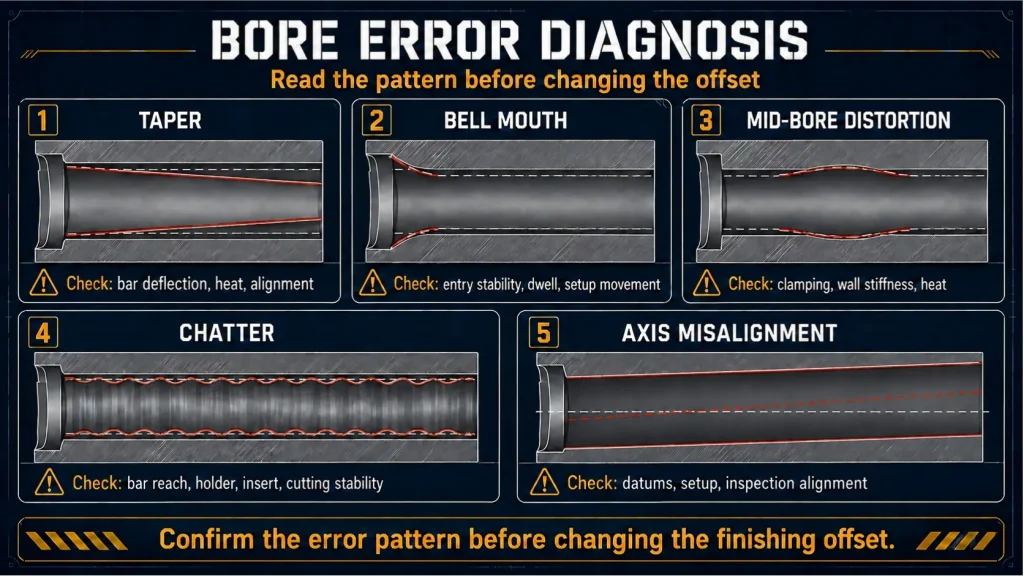
This diagnosis should occur before repeatedly changing the finishing offset.
The pattern identifies whether the next action belongs in tooling, workholding, cutting conditions, thermal control, deburring, or inspection.
Measure Size, Form, and Location Separately
A single measuring tool rarely proves every functional characteristic of a precision bore.
| Inspection method | Useful for | What it does not prove by itself |
|---|---|---|
| Pin or plug gauge | Limit check for a suitable bore size or fit | Actual diameter, taper, axis location, or complete form |
| Two-point bore gauge | Comparative diameter readings at different depths and directions | Full roundness or bore position without additional methods |
| Three-point internal micrometer | Self-centering size checks and detection of some diameter variations that a two-point check may miss | Complete roundness; response depends on contact geometry and lobe order; it does not prove axis location or surface roughness |
| CMM | Bore location, axis orientation, relationships to datums, and sampled size/form | Complete fine-scale surface or form unless access and sampling strategy are suitable |
| Roundness or cylindricity equipment | Detailed form error along selected sections or paths | Assembly fit, datum location, or surface texture unless separately evaluated |
| Surface profilometer | Specified roughness parameters on an accessible internal surface | Bore diameter, axis relationship, or hidden burrs |
| Borescope or visual inspection | Internal scratches, chips, burrs, and bottom condition | Quantified diameter or geometric tolerance |
A bore gauge should be set against an appropriate master and used with a defined technique.
Measurements at the mouth, middle, and far end can reveal taper, while readings in more than one angular direction can indicate ovality. These readings still do not equal a complete roundness trace.
A three-contact instrument may reveal some odd-lobed conditions that a two-point diameter reading misses. Its response still depends on contact spacing and the number and phase of the lobes.
Neither a two-point nor a three-point size reading should be presented as complete roundness verification.
A CMM can be valuable when the bore axis must relate to mounting datums or another feature. It should not be selected automatically for a tiny, deep, high-aspect-ratio bore.
Probe access, stylus length, sampling strategy, alignment, and the required report all affect the result.
Our quality assurance for CNC machined parts explains how inspection methods and reports can be selected according to feature geometry, tolerance, and project requirements.
Put the Functional Bore Requirements on the Drawing
The drawing should state what makes the bore acceptable. A useful specification may include:
- Nominal diameter with a dimensional tolerance or defined fit system
- Finished depth and whether the hole is through or blind
- Bottom shape, internal shoulder, relief, and allowable corner radius
- Datums controlling bore position or orientation
- Required relationship to an outside diameter, face, or second bore
- Cylindricity, straightness, position, perpendicularity, or runout only where function needs it
- Surface-roughness requirement on the functional length
- Edge break and internal cross-hole burr requirements
- Material grade and heat-treatment condition
- Whether the bore requirement applies before or after coating or finishing
- Inspection method, report scope, and sampling requirement when these are contractually important
Avoid an unsupported note such as “bore must be concentric” without identifying the referenced feature, datum, tolerance value, and inspection expectation.
The machinist and inspector need the same functional definition.
If a fit designation such as H7 is used, identify the governing standard and consider the mating shaft, bore depth, material, operating temperature, and finishing route.
The CNC machining tolerances guide provides broader guidance on fit classes, deep-hole risk, post-finish inspection, and concentrating narrow tolerances on functional features.
What Makes Boring More Expensive
Boring cost rises when the process needs more stability, more setups, slower verification, or a secondary finishing operation.
Common cost drivers include:
- A small bore diameter combined with a long depth
- Tight diameter tolerance across the full functional length
- Cylindricity, straightness, position, perpendicularity, or runout requirements
- Blind bottoms, internal shoulders, grooves, or multiple stepped diameters
- Cross holes and internal burr-control requirements
- Thin walls or clamping-sensitive rings and sleeves
- Cast or forged pre-holes with uncertain stock distribution
- Hard, abrasive, gummy, or heat-sensitive materials
- A surface finish that cannot be reached by a stable boring pass alone
- Final sizing after plating, coating, heat treatment, or another secondary process
- Dedicated gauges, master rings, extended probes, detailed reports, or full-batch inspection
A larger diameter tolerance does not automatically make the bore inexpensive if its axis must be closely related to another feature.
Conversely, a selective tight diameter on a short, accessible, rigid bore may be more practical than a looser specification applied through a long flexible section.
The quotation should therefore separate diameter, geometry, datum relationship, finish, depth, and inspection rather than treating them as one “precision bore” requirement.
Four Boring Assumptions That Cause Inspection Disputes
Can boring make an existing hole smaller?
No. Boring removes material and enlarges the hole.
An oversized bore may require a design change, sleeve, insert, coating buildup, welding and remachining, or part replacement. The repair route depends on material, load, temperature, and approval requirements.
Is boring more accurate than reaming?
Neither process is universally more accurate.
Boring is adjustable and can influence the bore axis and internal geometry relative to the setup. Reaming may provide efficient size consistency and finish when the starting hole has a small, uniform allowance and an acceptable path.
The required correction determines the process.
Does a bore gauge prove cylindricity?
Not by itself.
A bore gauge can compare diameter at several depths and orientations and may expose taper or ovality. A complete cylindricity requirement may need a suitable form-measurement system or a validated CMM strategy.
Can a caliper inspect a precision bore?
Caliper inside jaws may be useful for a general check on a large accessible bore, but they are usually unsuitable for verifying a narrow functional fit, deep diameter, taper, or geometric relationship.
Select the gauge according to the tolerance and acceptance method.
Review a Precision Bore Before Quotation
For a useful boring review, provide more than the finished diameter. Include:
- Starting-hole diameter and whether it is drilled, cast, forged, or previously machined
- Finished bore diameter, tolerance, depth, and functional length
- Through-hole or blind-hole condition and bottom geometry
- Datum scheme and required position, orientation, runout, or related geometry
- Mating shaft, bearing, sleeve, seal, or assembly-fit information
- Surface-roughness requirement and any lay or sealing concern
- Cross holes, internal grooves, shoulders, and burr requirements
- Material grade, hardness, and heat-treatment condition
- Coating, plating, anodizing, or other post-processing requirements
- Required inspection method, report content, and production quantity
Rapid Efficient can review material behavior, starting-hole condition, machining strategy, bar-access risk, tolerance allocation, finishing, inspection, packaging, and delivery requirements before quotation.
For deep bores, specialized finishing, or unusual equipment needs, the feasible process route should be confirmed against the drawing before an order is accepted.