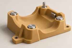
A freshly face-milled surface can look bright and uniform but still fail its functional requirement.
The face may bow after the clamps are released. Adjacent cutter passes may leave a measurable step. One insert may create a dominant circular track. A sealing surface may meet its roughness requirement but fail flatness, while a visually imperfect mounting face may still be dimensionally acceptable.
Face milling is therefore not simply a matter of moving a large cutter across the top of a part. The final surface is produced by a complete system:
- Cutter geometry
- Insert position and condition
- Toolholder and spindle behavior
- Cutter engagement
- Programmed path
- Workholding support
- Material stability
- Part temperature
- Inspection state
A useful face milling plan starts with the function of the surface, not the appearance of the cutter marks.
Define the Functional Face Before Choosing the Cutter
The first question should not be:
Which face mill should the shop use?
It should be:
What must this surface do after the part is unclamped, finished, inspected, and assembled?
Different faces require different controls.
| Surface Function | Characteristics That May Matter | Hidden Failure Risk |
|---|---|---|
| Datum face | Flatness, cleanliness, protected edges | An unstable datum transfers error into later setups and inspection |
| Mounting face | Flatness, parallelism, contact area | A visually smooth face may rock or distort the assembly |
| Sealing face | Flatness, roughness, lay direction, scratches, burrs | Tool marks or local steps may create a leakage path |
| Sliding face | Parallelism, roughness, waviness, edge condition | Local ridges may create uneven contact or wear |
| Heat-transfer face | Flatness, contact area, surface condition | Bowing or high spots may reduce functional contact |
| Cosmetic face | Tool-mark consistency, scratches, dents, color after finishing | A dimensionally acceptable surface may still fail visual inspection |
| Stock-preparation face | Material removal, datum creation, allowance control | Removing too much stock may affect later dimensions or stability |
Not every face needs a tight flatness tolerance, a low roughness value, and a cosmetic tool pattern at the same time.
Applying all three without a functional reason can increase cycle time, require an additional finishing pass, restrict cutter selection, and add inspection work without improving the part.
For custom parts, the broader CNC milling services page explains the commercial machining scope. The engineering decision here is narrower: how the required face function should control the cutter, setup, path, and inspection plan.
Face Milling Is Not Side Milling With a Wider Tool
In face milling, the cutter axis is generally perpendicular to the machined surface. The cutter’s inserts remove material as the tool travels across an open face.
A face mill is commonly suitable for:
- Creating an initial datum surface
- Removing stock from plates, blocks, castings, or forgings
- Machining mounting and contact faces
- Producing broad external flat surfaces
- Roughing or finishing an accessible pocket floor
- Preparing a surface for a later setup
An end mill can also machine a flat face, especially on small surfaces or where access is limited. However, a dedicated face mill may cover a wider area and distribute the cut across multiple replaceable inserts.
Face milling becomes less attractive when:
- The surface is inside a narrow pocket
- Walls prevent the cutter body from clearing the part
- A square shoulder must be produced at the same time
- The machine cannot support the cutter diameter or required power
- The workpiece is too flexible to resist the cutting and clamping forces
- The required final form needs grinding, lapping, or another process after milling
- The part moves significantly after material removal
A large face mill does not correct unstable material or poor workholding. It can machine the restrained workpiece accurately and still release a bowed part.
The Cutter Does Not Create Flatness by Itself
A face mill generates a surface from the rotating path of its cutting edges. That path depends on more than the cutter body.
Machine and spindle geometry
The spindle axis and machine motion affect how the cutter plane passes over the workpiece. Misalignment may produce uneven cutting between the leading and trailing sides of the cutter, unexpected crosshatch, local back-cutting marks, or a surface that changes across its width.
The pattern alone does not prove that the spindle is misaligned. Insert height variation, cutter-body runout, workpiece movement, and path overlap can create similar evidence. The condition should be isolated before adjusting machine geometry.
Toolholder and cutter connection
Contamination, damage, or poor seating at the spindle taper, toolholder, arbor, or cutter interface can introduce runout or tilt.
Cleaning only the visible cutting edge may not solve the problem. The complete stack from the spindle to the insert seats should be considered.
Workpiece support
A rigid block supported close to the cutting area behaves differently from a thin plate bridging open fixture areas.
If the workpiece bends under clamp pressure, the cutter may machine a flat plane while the part is restrained. After unclamping, the stored elastic deformation is released and the surface changes.
Material condition
Rolled plate, flame-cut stock, castings, forgings, heat-treated material, and previously rough-machined parts may contain different residual-stress patterns.
Removing material from one side can disturb the existing balance. The resulting movement may appear during cutting, after unclamping, after a waiting period, or after thermal processing.
Flatness is therefore a system result. Cutter choice is important, but it is only one part of the system.
Read Feed Marks, Crosshatch, Steps, and One-Insert Witnesses
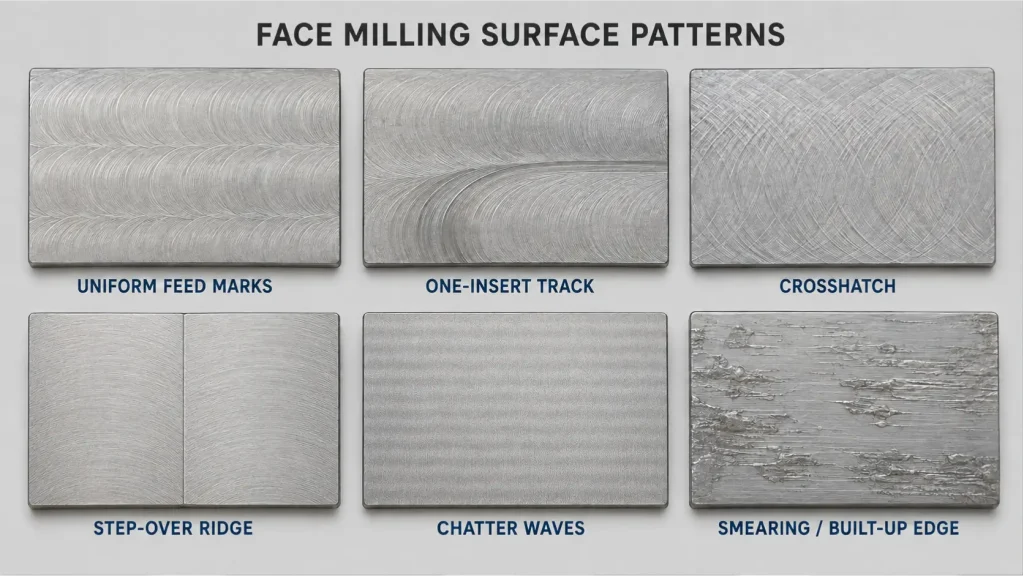
A face-milled surface contains information about the process.
Some marks are normal consequences of the cutter path. Others indicate that only one insert is controlling the finish, the part is moving, or adjacent passes are not meeting in the same plane.
Uniform feed arcs
Consistent arcs or feed marks may be normal when their spacing and depth remain stable and the surface meets the specified roughness and functional requirements.
A visible pattern is not automatically a defect.
One dominant circular track
If one repeated track is noticeably deeper or brighter than the rest, one insert may be projecting farther in the axial direction. Cutter-body runout, an improperly seated insert, debris in an insert pocket, insert variation, or toolholder runout may contribute.
The protruding insert can become the effective finishing edge even though several inserts are installed.
Crosshatch or trailing-edge marks
A light crosshatch may appear when the trailing side of the cutter also contacts the surface. Depending on the cutter geometry, machine alignment, path, and acceptance requirement, this may be expected or may indicate unwanted back cutting.
The pattern should be evaluated against roughness, flatness, appearance, and function instead of being rejected from appearance alone.
Ridges between adjacent passes
A ridge or step between tool paths may be associated with:
- Cutter tilt
- Tool or spindle runout
- Different cutting loads between passes
- Tool deflection
- Thermal drift
- Workpiece movement
- Z-axis repeatability
- Uneven finishing allowance
- Insert wear or built-up edge
Reducing the programmed step-over may hide some visual evidence, but it does not necessarily remove the underlying plane mismatch.
Periodic waves
Regular waves or alternating bands may indicate vibration. Possible contributors include cutter pitch, insert condition, spindle speed, part stiffness, fixture support, toolholder behavior, or interrupted engagement.
Changing only the feed rate may move the symptom without removing the source.
Smeared or torn areas
Smearing can occur when the cutting edge rubs, the material adheres to the insert, chips are recut, or the edge is no longer sharp enough for the material and allowance.
This is especially important on ductile materials such as aluminum and copper, but the mechanism and corrective action depend on the material condition and cutting system.
A surface pattern is evidence, not a diagnosis.
Cutter Diameter Changes Entry, Exit, and Cutting Load
A cutter wider than the workpiece may complete the surface in one pass. That can eliminate path-to-path steps, but it is not automatically the most stable or economical choice.
A larger cutter can also:
- Engage more inserts
- Require more spindle power and torque
- Increase the effect of cutter-body or insert runout
- Change the direction and magnitude of cutting forces
- Extend farther beyond the supported cutting area
- Require more clearance around clamps and part features
- Produce different entry and exit behavior
A smaller cutter may fit around obstacles and reduce the engaged cutting load in some setups, but the actual load still depends on cutter pitch, engagement, depth of cut, feed per tooth, and material. It also usually requires multiple passes.
Those passes introduce another risk: visible or measurable steps where adjacent paths meet.
Cutter position matters as much as nominal diameter. The programmed path affects:
- How each insert enters the material
- How chip thickness develops
- How many teeth remain engaged
- Where the cutter exits
- Where burrs are likely to form
- Whether the trailing side contacts the finished surface
Centering the cutter path on the workpiece is not automatically the most stable choice. For suitable open faces, an off-center path combined with the appropriate cutter rotation and feed direction can create a more favorable entry and exit sequence and help the chip become thinner toward exit.
The amount of offset should be selected from cutter diameter, workpiece width, entering angle, insert engagement, clamp clearance, and cutter-manufacturer guidance rather than copied as a fixed percentage.
A roll-in entry is a separate programmed transition that may reduce abrupt edge loading when the geometry permits.
The entering angle also changes chip thickness and force distribution.
A 45-degree cutter usually directs a larger share of the cutting force axially into the workpiece support, while a near-90-degree cutter shifts more of the force radially.
Axial loading can help a well-supported part remain seated, but it may deflect an axially weak thin floor or unsupported plate. A near-90-degree cutter may be reviewed for that geometry together with sharp positive inserts and a controlled cutting load, although the increased radial force can create different fixture or wall-deflection risks.
The appropriate entering angle depends on part stiffness, support direction, shoulder requirements, material, machine capability, and the finishing objective.
The cutter should therefore be selected with the complete pass in mind, not from face width alone.
When One Insert Determines the Whole Surface
Multi-insert face mills depend on the cutting edges occupying a controlled axial relationship.
If one insert projects farther than the others, it may remove most of the final material. The other inserts may still contribute to stock removal, but the high insert leaves the dominant finishing trace.
Possible causes include:
- Debris under the insert
- A damaged insert pocket
- Incorrect insert seating
- Uneven screw tightening
- Mixed or inconsistent inserts
- Chipped or worn cutting edges
- Cutter-body damage
- Toolholder or spindle runout
- Incorrect setup of adjustable cartridges
A wiper insert is different from an accidental high insert.
Some fixed-pocket cutter systems position a designated wiper slightly farther toward the workpiece, while adjustable cartridge systems may require a manufacturer-defined setting. Other finishing cutters use precision seats or integrated wiper facets without a separate shop adjustment.
The required position is therefore cutter-specific and should not be generalized from a universal offset value.
Spindle tram and feed direction can also change trailing-edge or broad wiper contact, so the cutter setup and resulting surface pattern should be confirmed before production.
When a dominant insert track appears, the shop should not begin by changing the drawing tolerance. A more useful sequence is:
- Clean and inspect the insert pockets.
- Confirm that the inserts belong to the intended cutter system.
- Check cutting edges for wear, chipping, or built-up material.
- Verify insert seating and fastening.
- Check cutter and toolholder runout.
- Run a controlled test cut.
- Compare the new pattern with flatness and roughness measurements.
This separates a cutter-stack problem from a programming or fixture problem.
Why a Light Finishing Pass Can Start Rubbing
A light finishing pass sounds safe because it applies less cutting force. That conclusion is incomplete.
If the remaining material is too small relative to insert runout, edge preparation, workpiece variation, or material recovery, some cutting edges may not form a stable chip. They may rub, polish, smear, or intermittently touch the surface instead.
Possible results include:
- Heat without effective material removal
- Built-up edge
- Surface smearing
- Inconsistent appearance
- Rapid edge wear
- Work hardening in susceptible materials
- Previous roughing marks remaining on the face
- One insert performing nearly all the finishing work
The answer is not necessarily a heavier cut. The finishing allowance should be matched to the insert geometry, material, cutter runout, part stiffness, and required surface.
A controlled process may use:
- A roughing pass that leaves consistent material
- A semi-finishing pass where geometry or distortion needs reassessment
- A final pass with sufficient chip formation
- Stable entry and exit
- Continuous chip evacuation
- No unnecessary dwell on the finished surface
- Inspection after the part reaches an appropriate condition
Cutting direction also affects chip formation, rubbing, burr location, and fixture loading. The climb milling vs conventional milling guide explains why neither direction should be selected without considering the part and setup.
Why the Face Can Move After the Clamps Release
A part can be flat while clamped and bowed after release.
This often occurs because the machining and inspection states are different.
Clamp-induced deformation
If clamps force a distorted blank against the fixture, the cutter machines the restrained shape. Once the clamps are removed, the blank returns toward its original form.
Excessive clamp force is not the only cause. Poor support location, chips under the part, high spots on the fixture, inconsistent clamp sequence, or a large unsupported span can also affect the surface.
Residual-stress redistribution
Removing stock changes the stress balance inside the material. Risk may increase when:
- A large amount of material is removed from one side
- The part has a thin final section
- The blank contains nonuniform residual stress
- Roughing exposes a different material layer
- Heat treatment occurred before or between machining operations
- Opposing faces receive very different material removal
Possible process responses include balanced stock removal, staged roughing, support closer to the cutting zone, lower-distortion workholding, intermediate dimensional checks, or finishing after the geometry has been reassessed.
These are process options, not universal instructions. The suitable route depends on the material, stock form, geometry, tolerance, quantity, and inspection state.
Thermal condition
A part measured immediately after a demanding cut may not represent its later stable condition. Workpiece temperature, fixture temperature, coolant condition, and inspection-room temperature can all affect a sensitive measurement.
For thin or tightly controlled parts, the drawing and inspection plan should clarify whether the part is evaluated:
- While clamped
- Immediately after machining
- Freely supported
- In a defined restrained condition
- After thermal stabilization
- After coating or another finishing process
- In its assembled functional state
Without that definition, the supplier and buyer may measure different versions of the same surface.
Face-Milled Surface Signature Diagnostic Map
The following map helps connect visible evidence to the next useful check. It does not claim that a surface pattern proves one root cause.
| Observed Surface Pattern | Possible Mechanisms | Misleading First Conclusion | Cutter or Setup Check | Required Confirmation |
|---|---|---|---|---|
| Uniform, consistent feed arcs | Stable cutter path and regular insert engagement | “Visible marks mean the face failed” | Confirm insert condition and path consistency | Compare with roughness, flatness, and cosmetic criteria |
| One dominant circular sweep | High insert, axial runout, dirty insert seat, cutter or holder runout | “Feed is too high” | Inspect insert height, seating, cutter body, holder, and spindle | Runout check plus roughness measurement |
| Crosshatch or trailing-edge facets | Back cutting, spindle alignment, cutter geometry, insert height variation | “The spindle is definitely out of tram” | Compare leading and trailing contact and inspect the cutter stack | Flatness map, controlled test cut, and machine check when justified |
| Ridge between adjacent passes | Plane mismatch, cutter tilt, deflection, thermal drift, uneven allowance | “The step-over is too large” | Check Z consistency, cutter load, insert condition, and workpiece movement | Measure step height and overall surface form |
| Repeating waves or bands | Chatter, variable tooth loading, flexible part, unstable holder or fixture | “Only the spindle speed is wrong” | Review cutter pitch, insert wear, support, engagement, and overhang | Surface measurement and controlled parameter test |
| Smeared or torn patches | Built-up edge, rubbing, dull edge, chip recutting, unsuitable geometry | “The material cannot be face milled” | Check edge condition, chip evacuation, allowance, and coolant strategy | Inspect insert deposits and compare a controlled pass |
| Exit burr or edge breakout | Exit direction, material ductility, worn insert, unsupported edge | “Deburring will fix it” | Review cutter exit, edge support, insert condition, and stock | Burr inspection and functional-edge review |
| Clean appearance but poor released flatness | Clamp deformation, residual stress, thermal change, unsupported geometry | “The cutter is inaccurate” | Inspect support, clamp sequence, stock removal, and part temperature | Measure in the required free or restrained state |
The map prevents a common troubleshooting error: changing cutting data before identifying whether the failure belongs to the cutter, machine, workholding, material, or inspection method.
Inspect Roughness, Flatness, and Parallelism Separately
One measurement cannot confirm every requirement on a face-milled surface.
| Characteristic | What It Controls | Possible Inspection Approach | Common Mistake |
|---|---|---|---|
| Surface roughness | Local microtexture | Roughness tester with an agreed direction, cutoff, and evaluation method | Approving roughness from visual appearance |
| Flatness | Surface form without a datum reference | Surface plate and indicator, CMM sampling or scanning, or another agreed method | Measuring only a few thickness points |
| Parallelism | Surface orientation relative to a datum | Indicator, height measurement, CMM, or functional setup relative to the datum | Treating parallelism as the same as flatness |
| Step between cutter passes | Local height discontinuity | Indicator scan, profilometer, CMM, or suitable comparison method | Assuming the visible line has no measurable height |
| Waviness | Longer-spaced surface variation | Profile measurement or agreed scanning method | Treating an acceptable Ra value as proof of low waviness |
| Cosmetic appearance | Visible uniformity, scratches, stains, and tool-mark acceptance | Controlled visual inspection and an approved reference when needed | Using an unspecified word such as “smooth” |
| Released-part geometry | Shape after unclamping or processing | Defined support and measurement state | Inspecting only while the part remains forced against the fixture |
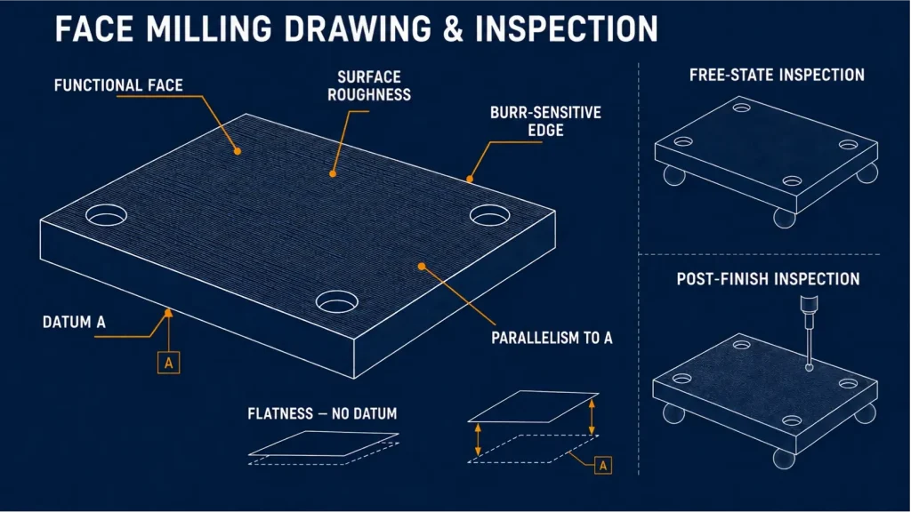
Flatness does not use a datum reference. Parallelism does.
A face can satisfy flatness but still be tilted relative to the mounting datum.
A surface that satisfies parallelism must remain inside a tolerance zone formed by two planes parallel to the referenced datum over the evaluated extent. A separate, tighter flatness requirement may still be needed when local contact or surface form has a stricter functional limit.
A roughness tester measures texture along its evaluation path. It does not automatically prove overall flatness, parallelism, waviness, or full cosmetic uniformity.
For broader control of dimensional and geometric requirements, review the CNC machining tolerances guide.
Inspection coverage should match the failure risk. A large sealing or mounting face may require more than one local reading, while a cosmetic face may need controlled lighting and an agreed acceptance reference in addition to dimensional checks.
When dimensional reports, surface checks, CMM inspection, or other evidence are required, the scope should be agreed before production through the quality assurance process.
What the Drawing and RFQ Must Define
A 3D model may define the nominal geometry but still leave the face-milling acceptance criteria unclear.
The drawing or purchasing specification should identify the information that protects the actual function.
| Face-Milling Requirement | What to Define | Why It Matters |
|---|---|---|
| Controlled face | Mark the exact face or bounded area | Prevents inspection of the wrong surface |
| Functional purpose | Datum, mounting, sealing, sliding, thermal contact, or cosmetic | Guides process and inspection priorities |
| Datum relationship | Required datum and precedence when orientation matters | Separates flatness from parallelism or profile |
| Flatness | Tolerance and evaluated extent | Controls form over the intended area |
| Parallelism | Tolerance relative to the correct datum | Controls assembly orientation |
| Roughness | Parameter, value, measurement direction, and standard context when needed | Prevents visual inspection from replacing texture measurement |
| Lay or tool-mark restriction | Permitted or prohibited directional marks | Important for sealing, sliding, and cosmetic surfaces |
| Local steps | Whether pass-to-pass ridges are functionally restricted | A low Ra value may not reveal a local step |
| Edge condition | Burr-sensitive, sealing, locating, or protected edges | Exit burr removal may damage the functional face |
| Part state | Free, supported, restrained, thermally stable, or assembled | Prevents contradictory inspection results |
| Processing state | Before or after coating, heat treatment, polishing, or other finishing | Later processing may change dimensions or surface condition |
| Inspection evidence | Characteristics, method, coverage, sample size, and report type | Aligns quotation and acceptance expectations |
The buyer usually does not need to specify the exact cutter brand, insert grade, spindle speed, or programmed path. Those are manufacturing decisions unless a qualified process has been contractually defined.
The buyer should define what the completed face must do.
Cost may increase when the requirement needs:
- Multiple roughing and finishing stages
- Balanced material removal
- A dedicated cutter or wiper system
- Reduced engagement or slower passes
- Additional setups or fixture support
- Tool-runout checks
- Thermal stabilization
- Broad-area flatness mapping
- Post-finish inspection
- Controlled cosmetic acceptance
- Additional parts or coupons for process validation
A tight surface requirement can be economical when it protects a real function. It becomes expensive when flatness, parallelism, roughness, appearance, and inspection coverage are all tightened without identifying the failure they are intended to prevent.
Send the Surface Definition, Not Only the 3D Model
For a useful face-milling review, provide:
- The controlled face and its function
- Face length and width
- Material grade and condition
- Starting stock form
- Expected machining allowance
- Flatness requirement
- Parallelism or datum relationship
- Surface roughness requirement
- Permitted or prohibited tool marks
- Burr-sensitive or sealing edges
- Free-state or restrained inspection requirement
- Coating, heat treatment, or polishing route
- Required inspection method and report
- Quantity and final assembly condition
Rapid Efficient can review cutter access, stock-removal strategy, workholding risk, surface requirements, datum relationships, finishing state, and inspection needs before quotation.
The objective is not to remove every visible cutter mark. It is to produce and verify the surface condition that the part actually requires.