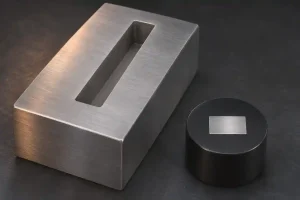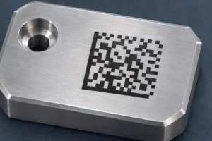

Approve a Data Matrix mark as part of the finished CNC component. Its location, encoded data and acceptance checks belong in the drawing and purchase requirements before the supplier chooses a marking route.
A phone successfully scanning the code proves only that the particular device could decode it under those conditions. It does not establish a specified mark-quality grade, confirm that the identifier belongs to that part, or show that the mark will survive later finishing.
For laser engraving a Data Matrix code on metal, settle four connected questions: where it can be read, how much space the data needs, which surface processes follow marking, and what evidence will release the batch.
Choose a Marking Face the Reader Can Reach
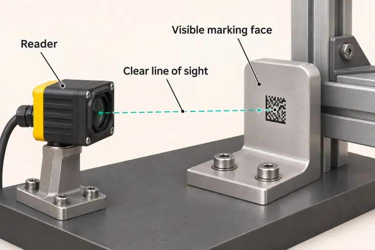
Start with the stage at which the code must be read. A code visible on a loose bracket may be hidden once the bracket is bolted into an assembly. A code inside a recess may be reachable by the laser but difficult for the receiving inspection system to illuminate and image.
Identify the reading stage as well as the marking location. Show the permitted face, position and orientation relative to identifiable part features. Include any assembly condition that limits access.
On a cylindrical surface, the code extends around a changing surface angle. That affects both how the mark is produced and how the reader sees it. Review curvature, viewing direction and working distance together. A flat marking pad may help, but adding one changes the part geometry and requires design approval.
Keep the marking area clear of sealing tracks, bearing fits, electrical contacts and other protected surfaces unless the design explicitly permits marking there. The permitted mark depth and surface alteration matter independently of readability. A readable code is not approval to remove material from a functional face.
The drawing should also identify the surface condition in the marking area. Machining texture, blasting, polishing and coatings can change reflected light and the contrast seen by the reader. An Ra value alone does not define those optical conditions.
Size the Code After the Data Is Fixed
Confirm whether the system requires ordinary Data Matrix ECC 200 or GS1 DataMatrix. GS1 DataMatrix has additional encoding and data-structure rules; it is not simply a different-looking pattern. Use the customer’s approved format rather than choosing one from the marking software’s default menu.
Settle the actual content before sizing the mark: part identifier, revision, batch or serial number, and any required separators. Preserve meaningful leading zeros and agree who assigns unique identifiers. A sample image cannot define how serial numbers change across the order.
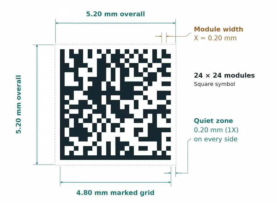
Each small cell in the grid is a module. Its nominal width is the X-dimension. More data may require a larger grid; keeping the same outside size would then make the modules smaller.
The surrounding quiet zone also needs space. The GS1 DataMatrix guideline specifies a minimum quiet zone one module wide on every side. Keep text, borders and other interfering features outside that clear margin.
Consider an illustrative 24 × 24-module grid, including its finder pattern, with X = 0.20 mm:
- Marked grid width: 24 × 0.20 = 4.80 mm.
- Quiet zone on each side: 0.20 mm.
- Grid plus the minimum quiet zones: (24 + 2) × 0.20 = 5.20 mm square.
A 5.00 mm-wide marking area cannot contain that particular layout at the stated module size. This is a geometric example, not a recommended module size or a guarantee of readability. Position tolerance, nearby edges and any human-readable text may require additional space.
Generate the code from the approved data, then check its actual module count and dimensions. Do not stretch it in one direction or reduce it merely to fit an illustration. Confirm the final layout against the applicable application requirements and the intended marking and reading equipment.
Approve the Mark After the Final Surface Process
The phrase “laser engraving” does not fully define the surface change. Engraving removes material, while other laser-marking methods can create contrast by changing the surface without making the same recess. The appropriate method depends on the alloy, coating, permitted surface alteration and service conditions.
Agree on the result and the allowed process before production. If the drawing requires a recessed mark, a contrasting surface mark is not automatically an equivalent. If material removal is restricted, requesting a deeper code to improve durability may conflict with the part requirement.
Map the marking operation into the actual surface-finishing sequence. Marking before anodizing, plating, blasting or coating means the code must remain acceptable after those operations. Marking afterward avoids covering the new mark with that finish, but may alter the finished surface locally. Neither order is a universal rule.
For the first approval, use a sample that represents the specified alloy, marking face and production finish. A mark demonstrated on a polished flat coupon does not by itself establish the result on a textured, curved production part. Coupons can help develop settings; the actual geometry still needs review.
Inspect the code in the required delivery condition. If it must remain readable after cleaning, wear, chemical exposure or another defined service condition, agree on a separate conditioning test and its acceptance criteria. An initial quality grade does not establish service life.
A later change in surface preparation, coating or marking settings can change the result. Decide which changes require renewed sample approval before treating the original sample as representative of repeat production.
Separate Decoding, Grading and Record Matching
A useful acceptance plan distinguishes three checks.
| Check | Evidence to retain | What the result does not establish |
|---|---|---|
| Decode the mark in the intended reading setup | Decoded string, part condition and agreed reader setup | A specified standardized quality grade or readability in every other setup |
| Verify the symbol’s optical quality | Report identifying the method, settings, grade and inspected symbol | That the encoded identifier belongs to the correct physical part, or that the mark will survive service |
| Match the data to the part and order | Comparison with the approved identifier list and required production records | Optical quality or durability of the physical mark |
Where formal direct part mark grading is required, specify the applicable standard and edition. ISO/IEC 29158:2025 modifies the ISO/IEC 15415 methodology for direct part marks, including illumination conditions, parameter measurements and grading.
Writing only “ISO-compliant barcode” leaves the acceptance criteria incomplete. Agree on the required grade, applicable test conditions and suitable verification equipment. Retain the reported settings, including illumination and measurement aperture where applicable. A reader’s confidence score should not be substituted for the specified verification result.
The production plan should state which checks apply to every part and which use an agreed sampling plan. Reading every serial number does not mean every mark has received a standardized quality verification. Conversely, grading a few samples does not detect every duplicate or incorrectly assigned identifier in a batch.
Compare decoded values with the approved data, not just the visible text beside the code. Control replacement parts, rejected parts and re-marking so that identifiers are not duplicated or reassigned without authorization. Agree on how marking records will be supplied and retained.
When the code points to a material or processing record, verify that connection separately. A correctly encoded heat number cannot repair a missing link between the stock and the machined component. The material-certification guide explains that document-to-part relationship.
For a CNC machining review, send the drawing with the permitted marking face and area, approved data format, serial-number responsibility, final surface condition and required acceptance evidence. Include the intended reading setup or its requirements. Rapid Efficient can review the marking sequence and inspection scope with the machining route; any required grading method and equipment availability should be confirmed before quotation.