
A finished shaft diameter and an electroless nickel thickness range share the same tolerance budget. If machining uses the full diameter tolerance before plating, a coating that meets its own requirement can still leave the finished shaft outside its size limits.
For electroless nickel plating on fitted CNC parts, define the deposit, its permitted thickness range and its final treatment condition together. Then work backward to the machining dimensions and identify where the coating must be checked.
This article covers nickel-phosphorus deposits, often called EN or EN-P. Nickel-boron and composite deposits need their own specifications. If the coating family is still undecided, our nickel vs zinc plating comparison explains the different protection mechanisms.
Specify the Deposit Before Setting the Allowance
Electroless nickel-phosphorus forms through an autocatalytic chemical reaction on a properly prepared surface. It does not use an external plating current. That distinction helps explain its thickness distribution, but it does not make every EN deposit equivalent.
Phosphorus content affects the coating’s properties. Lower-phosphorus deposits can suit requirements for high hardness in the as-plated condition or resistance to strongly alkaline environments. Higher-phosphorus deposits are often considered for corrosion resistance in acidic environments. Neither description replaces an assessment of the actual chemicals, temperature, exposure and final coating condition.
ASTM B733 separates nickel-phosphorus coatings by composition, service condition with associated minimum thickness, and post-plating heat treatment. A drawing should identify the applicable specification and revision, together with the required classifications.
Use a defined phosphorus range or the relevant standard designation when composition matters. Labels such as “medium phosphorus” can cover different ranges in supplier literature.
A minimum coating thickness addresses only one side of a fitted-feature requirement. The drawing may also need a maximum thickness to limit dimensional buildup. Confirm that both can be achieved on the specified surfaces.
Work Backward from the Finished Diameter
For a uniformly coated plain shaft, the diameter increases by twice the radial coating thickness:
Finished diameter = pre-plating diameter + 2 × coating thickness.
Consider an illustrative shaft with these requirements:
| Requirement | Illustrative limits |
|---|---|
| Finished shaft diameter | 20.000–20.030 mm |
| Coating thickness on the cylindrical surface | 0.020–0.030 mm per side, or 20–30 μm |
| Diameter increase from the coating | 0.040–0.060 mm |
Assume one fixed pre-plating diameter range must remain acceptable with any coating thickness within those limits. The smallest pre-plating diameter must still meet the finished minimum with the thinnest coating:
Minimum pre-plating diameter = 20.000 − 2 × 0.020 = 19.960 mm.
The largest pre-plating diameter must stay within the finished maximum with the thickest coating:
Maximum pre-plating diameter = 20.030 − 2 × 0.030 = 19.970 mm.
Only a 0.010 mm pre-plating diameter window remains in this simplified example. The 0.010 mm range in coating thickness per side consumes 0.020 mm of the finished diameter tolerance.
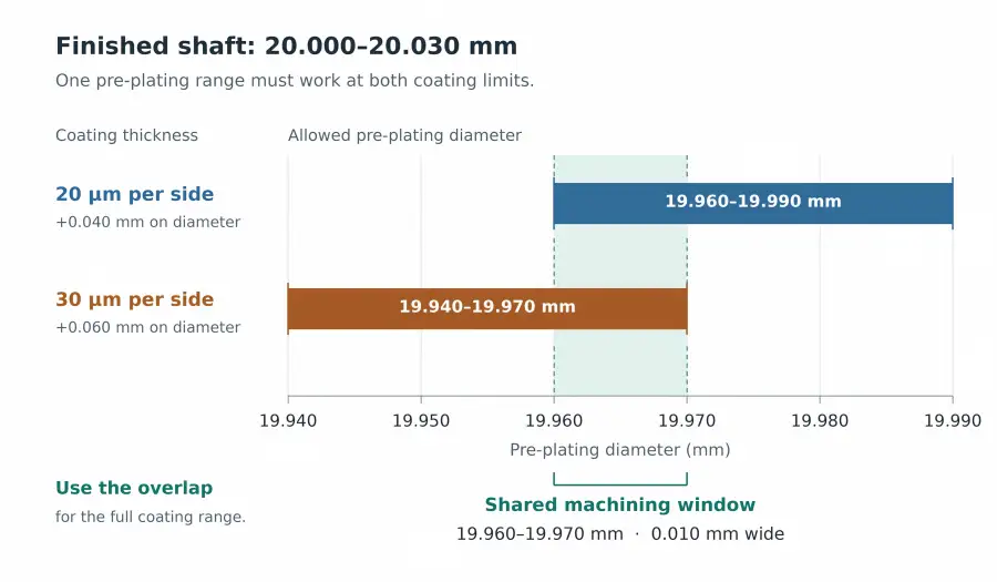
Subtracting only the nominal coating thickness would miss that effect. Using a nominal 0.025 mm per side to shift the complete finished size range would give 19.950–19.980 mm before plating. Combining those limits with the permitted coating range could produce finished diameters from 19.990 to 20.040 mm. Both extremes fall outside the required 20.000–20.030 mm range.
The example assumes uniform radial deposition, no material removal during preparation, no later grinding and no heat-treatment distortion. The numbers are not recommended coating limits or a stated production capability. A real plan must account for those effects and measurement uncertainty; dimensions specified before chemical preparation may need a separate allowance.
If the remaining size window is impractical, review the coating range, the functional fit or a controlled finishing operation after plating. Each option changes the manufacturing plan. Grinding afterward also requires a specified remaining coating thickness on the finished surface.
For bores, coating reduces the diameter. Thread allowances depend on the thread geometry and cannot be copied from the plain-shaft calculation. Connect these decisions to the final drawing requirements using the broader CNC machining tolerances guide.
A Thickness Requirement Needs a Location
Electroless deposition can provide relatively even buildup on complex shapes when solution reaches and circulates over the prepared surfaces. A deep bore, narrow recess or trapped pocket still needs a process review. An accessible outside surface does not establish what happened inside the part.
Mark the surfaces where thickness is functionally important, together with any areas that must remain unplated. The following distinctions help turn a general EN note into a usable coating plan.
| Part region | What the drawing should distinguish | What must be confirmed |
|---|---|---|
| Fitted external journal | Final diameter and local coating minimum and maximum | The machining and coating ranges fit within the finished size limits |
| Internal bore or recess | Required coated depth and local thickness limits | Preparation, solution access and a method that can evaluate the required location |
| Thread or surface to remain unplated | Masking boundary and permitted transition | Masking is feasible, and the exposed surface has an acceptable protection plan |
| Surface to be ground after plating | Final size, roughness and minimum remaining coating | Finishing will not remove the required functional layer |
Masking has practical limits at edges, recesses and small features. Resolve the permitted transition before production, especially where a bare-to-plated boundary lies near a fitted or exposed surface.
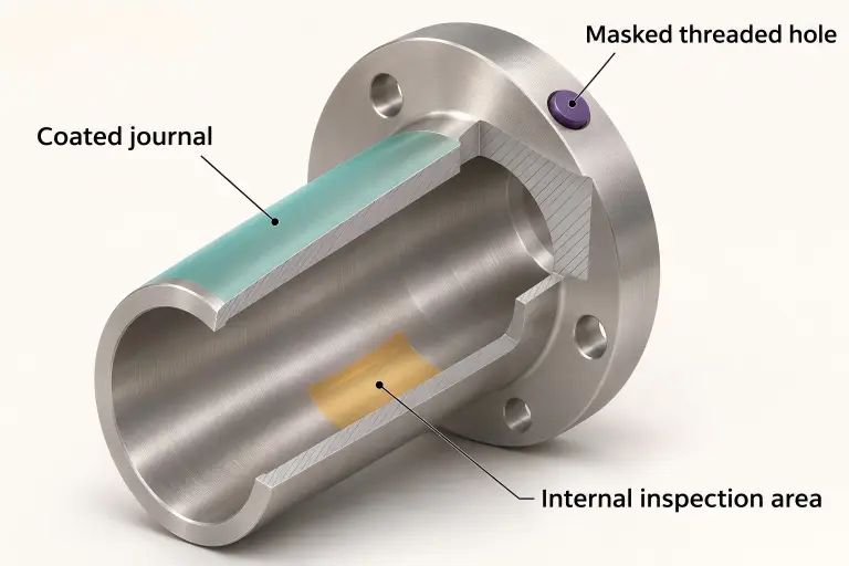
Select the thickness measurement method for the deposit, substrate and geometry. Record the measurement locations and acceptance limits. A flat witness coupon processed with the parts can support agreed tests, but it does not automatically demonstrate coverage at the bottom of a deep feature.
Likewise, a final diameter reading does not establish the local coating thickness unless the measurement method and assumptions support that conclusion. Both the finished dimension and the coating requirement need appropriate evidence.
Review the Heat Treatment with the Base Material
A note that says “heat treat after plating” leaves several different purposes unresolved:
- Deposit hardening: changes the coating structure to obtain a specified hardness.
- Adhesion treatment: improves bonding for a defined substrate and process.
- Hydrogen-embrittlement relief: addresses hydrogen-related risk in susceptible materials under the applicable specification.
Do not treat these as interchangeable cycles. A required relief treatment is not automatically satisfied by a separate hardness treatment, and a deposit-hardening cycle is not a universal instruction for every plated part.
For high-strength or hardened steel, provide the actual strength or hardness condition and heat-treatment history. The preparation route, applicable relief requirements and timing need review before processing. The absence of an external plating current does not remove that review.
The base material must also tolerate the proposed thermal cycle. Check the existing temper, required mechanical properties and dimensional stability, particularly for heat-treated aluminum alloys and hardened steels. A hard coating does not compensate for an unacceptable change in the substrate.
Hardening can create a trade-off with corrosion resistance. Advanced Plating Technologies describes how heat treatment changes EN deposit structure and corrosion behavior. Assess the required properties after the complete treatment sequence.
When coating hardness is an acceptance requirement, state the test method, test load, test location or agreed specimen, and supplied condition. Do not substitute the base material’s hardness result for the coating result.
These choices also explain quotation differences. A narrow coating range on a fitted journal, selective masking, internal-feature verification, thermal processing and final grinding represent different work from an unrestricted general coating. Compare quotations against the same defined requirements.
For review through our CNC machining services, send the drawing with the EN specification, phosphorus requirement, local thickness limits, finished fit dimensions and masking boundaries. Include the base material condition, permitted thermal processing and any planned finishing after plating. RapidEfficient can coordinate the machining, coating and inspection review with the relevant suppliers before quotation.