For carbon and alloy steel parts, zinc plating is often a starting point when corrosion protection is the primary requirement. Nickel plating deserves closer review when wear, surface hardness, or a controlled barrier layer also matters.
The important difference in nickel plating vs zinc plating is how the coating protects the steel—and what happens when that coating is damaged. The choice also changes the allowance needed on shafts, bores, and threads.
This comparison covers electroplated zinc, electrolytic nickel, and electroless nickel-phosphorus. Zinc-nickel alloy plating and hot-dip galvanizing require separate comparisons. Aluminum, stainless steel, and copper alloys also need their own preparation and coating reviews.
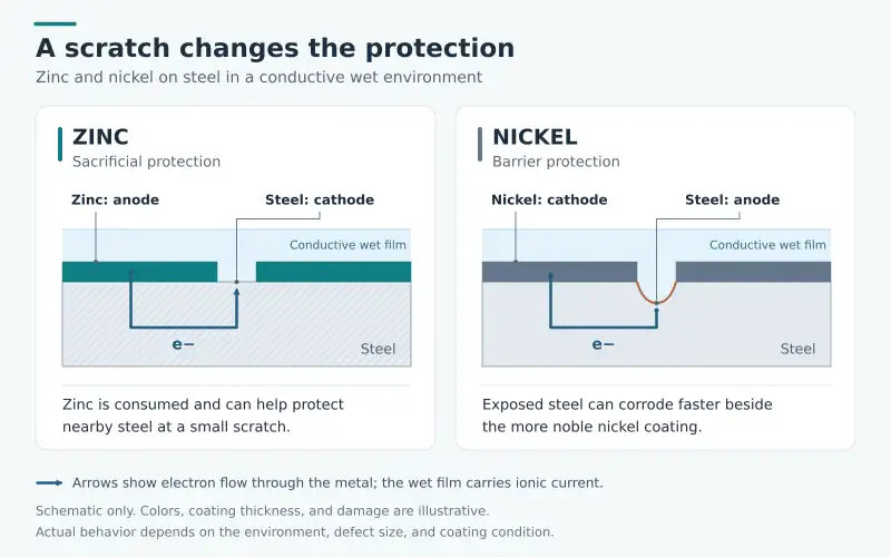
A Scratch Changes How Zinc and Nickel Protect Steel
Zinc provides both a physical barrier and sacrificial protection. In suitable wet conditions, zinc can corrode preferentially and help protect nearby exposed steel at a small scratch. This protection consumes zinc, so coating thickness, exposure, and damage size still matter.
Nickel generally protects steel as a barrier. In many wet environments, nickel is more noble than steel. If a pore or scratch exposes the steel, the exposed area can become a site of local corrosion. Nickel coating quality therefore depends on coverage, adhesion, porosity, and the complete layer system.
A damaged zinc coating and a damaged nickel coating do not protect the exposed steel in the same way.
This difference gives the comparison a useful starting point:
- If occasional scratches are expected and steel corrosion is the main concern, evaluate the zinc system’s remaining protective capacity.
- If a nickel layer must remain an effective barrier, review how wear, pores, edges, and handling damage could expose the steel.
Neither coating can be selected from appearance alone. A bright surface does not show whether a recessed feature has adequate coverage.
Specify Which Nickel Process You Are Comparing
“Nickel plated” leaves an important question unanswered: is the coating electrolytic nickel or electroless nickel?
Electrolytic nickel uses an external electrical current. Current distribution affects where the metal builds up. Edges and corners can receive more deposit than recessed areas, although bath chemistry, anode arrangement, racking, and other process controls influence the result.
Electroless nickel-phosphorus, often called EN or EN-P, deposits through a self-sustaining chemical reaction without an external plating current. Its properties depend on phosphorus content and subsequent heat treatment. ASTM B733 classifies these coatings by phosphorus composition, service condition and coating thickness, and post-treatment. Specify the required classifications rather than relying on “electroless nickel” alone. ASTM B733.
Where hardness or magnetic behavior matters, define the acceptance requirement in the final supplied condition. A deposit described as nonmagnetic does not make the steel substrate nonmagnetic.
Electroless deposition can provide more even coverage on complex shapes, but the solution must reach and circulate around the surface. Blind holes and small internal passages can still receive less coating.
Electroplated zinc also needs a complete specification. Thickness and supplementary treatments, such as conversion coatings or sealers, affect the finished system. ASTM B633 covers electrodeposited zinc on iron and steel; its scope also directs purchasers of threaded fasteners to consider ASTM F1941/F1941M. ASTM B633.
A useful comparison therefore identifies the actual systems: for example, a specified zinc deposit with a defined supplementary treatment versus a specified nickel-phosphorus deposit in its final heat-treated condition.
For a broader view of how these choices interact with machining, see our surface finishes guide.
Choose by the Surface That Must Keep Working
The following matrix translates the coating mechanisms into practical design questions. It is a selection aid, not a universal ranking.
| Part condition | Zinc route: key question | Nickel route: key question | Evidence needed before selection |
|---|---|---|---|
| An external steel surface may be scratched during use | Can the specified zinc system provide suitable sacrificial protection in this environment? | Can the barrier remain intact, or will damage expose steel? | Exposure, likely damage, coating system, and corrosion acceptance criteria |
| A shaft or contact face slides against another part | Will rubbing remove the protective layer too quickly? | Which deposit and final condition provide suitable wear behavior? | Mating material, load, motion, lubrication, and representative wear testing |
| A bore or recessed feature must be coated | Can the process achieve the required local thickness? | Would electroless nickel improve coverage, and can solution circulate adequately? | Feature depth, access, local thickness limits, and measurement locations |
| An electrical contact must remain stable | How will conversion coatings, sealers, and surface films affect contact? | How will the nickel deposit and any top treatment affect contact? | Mating finish, contact force, resistance limits, and testing after environmental exposure |
For a sliding surface, hardness alone does not establish service life. Contact pressure, debris, lubrication, substrate support, and the mating material can change the wear result.
Heat treatment also needs a clear purpose. A treatment used to harden electroless nickel can change its structure and reduce corrosion resistance relative to the same deposit before that treatment. Evaluate wear and corrosion in the final supplied condition. Advanced Plating Technologies discusses this heat-treatment tradeoff.
Electrical Contacts Need the Complete Finish System
For electrical contacts, comparing the bulk conductivity of nickel and zinc is insufficient. Surface films and the actual metal-to-metal contact spots affect resistance. Initial resistance and resistance after aging are both relevant when evaluating a connection.
For a plated grounding pad, specify the complete finish system, including any passivation or sealer. Define the assembly condition and the resistance limits before and after the relevant environmental exposure.
If masking is proposed, identify the layer to be excluded and how corrosion protection will be maintained. “Mask the grounding pad” should not leave the supplier guessing whether to omit the zinc deposit, the conversion treatment, or only the sealer.
If the joint also provides electromagnetic interference shielding, specify the required shielding test separately. A DC contact-resistance result alone does not establish high-frequency shielding performance.
Appearance should be specified separately from these functional requirements. Define visible areas and acceptable color or gloss variation; brightness is not a substitute for coating acceptance.
Budget Coating Thickness on Both Parts of a Fit
Both zinc and nickel plating add material. Even a uniform coating changes the size of a fitted feature.
For a simple cylindrical surface:
- Coating an external shaft increases its diameter by twice the radial coating thickness.
- Coating a bore decreases its diameter by twice the radial coating thickness.
- Coating both mating parts consumes clearance on both parts.
For uniform deposits, the geometric relationship is:
Final diametral clearance = initial diametral clearance − 2 × shaft coating thickness − 2 × bore coating thickness.
Consider this illustrative example. Assume a uniform coating thickness of 0.010 mm, or 10 μm, on each coated surface.
| Feature | Before plating | After plating |
|---|---|---|
| Shaft diameter | 10.000 mm | 10.020 mm |
| Bore diameter | 10.030 mm | 10.010 mm |
| Diametral clearance | +0.030 mm | −0.010 mm |
In this example, plating turns 0.030 mm of clearance into 0.010 mm of interference.
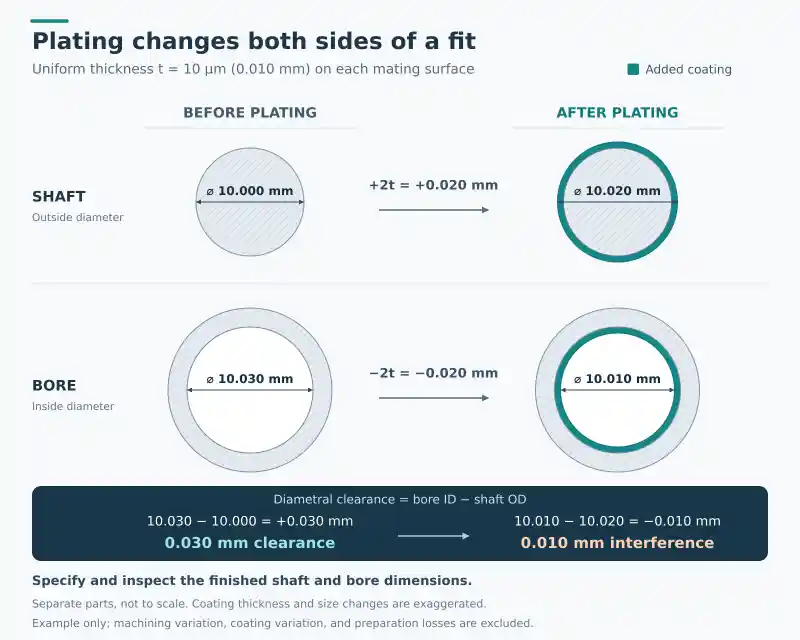
These values illustrate geometry; they are not a recommended coating thickness or a production capability. The example excludes machining variation, coating variation, and any material removed during preparation.
A production tolerance budget must include those effects. Check the maximum finished shaft size against the minimum finished bore size when evaluating the tightest assembly condition.
Electroless nickel can make thickness distribution easier to control, but uniformity does not remove the need for allowance.
Threads Need a Different Allowance
For an ideal 60° thread with a uniform coating thickness t measured perpendicular to the thread flank, the approximate pitch-diameter change is:
- External thread: increase of 4t.
- Internal thread: decrease of 4t.
This differs from the 2t diameter change for a plain cylinder. Twin City Plating illustrates the dimensional effect of plating on threads.
If both threads receive 10 μm on their flanks, the external pitch diameter increases by about 40 μm and the internal pitch diameter decreases by about 40 μm. The difference between the two pitch diameters therefore decreases by about 80 μm. This is not an 80 μm value for axial backlash.
The calculation alone does not show whether a 6g/6H thread pair will bind. Check the thread size, pitch, actual pre-plating limits, coating range, and required final gauging condition.
Agree any pre-plating size or tolerance adjustment before manufacturing. Cutting a plated thread afterward can remove its protective coating.
Our CNC machining tolerance guide explains how final feature requirements should connect to the machining and finishing plan.
Review Hardened Steel Before Selecting Either Route
High-strength or hardened steel requires attention to hydrogen embrittlement: hydrogen introduced during processing can reduce the steel’s ability to withstand load.
The review should cover the complete preparation and plating sequence. Electroless nickel’s lack of an external plating current does not, by itself, establish that the overall process is free of hydrogen-related risk.
Provide the steel grade, actual strength or hardness condition, heat-treatment history, and any surface hardening. The responsible engineer and finishing supplier should establish the applicable process controls, relief treatment, and verification requirements.
A bake is not a universal cure. ASTM B850 addresses post-coating treatments that may reduce susceptibility and explicitly notes that heat treatment does not guarantee freedom from hydrogen damage. ASTM B850.
Also check whether the material falls within the selected coating specification. ASTM B633 advises against zinc electroplating certain high-strength materials under that specification. A generic baking note does not override that limitation.
Keep hydrogen-embrittlement relief separate from heat treatment intended to harden a nickel deposit. Their purposes and required conditions must be reviewed independently.
Make the Drawing Describe the Finished Coating System
A drawing note such as “nickel plate” or “zinc plate” gives the supplier too much room to interpret the required finish.
Before release, resolve these coating-specific items:
- Process and specification: identify the coating route, applicable standard and revision, and required classification.
- Complete layer system: include required underlayers, conversion coatings, sealers, or top treatments.
- Thickness by location: identify surfaces that need minimum protection and features where maximum buildup limits fit.
- Final dimensions: state which dimensions and thread requirements apply after plating.
- Excluded surfaces: define masking boundaries, the treatment being excluded, and any permitted rack-contact locations.
- Material condition and heat treatment: identify the steel condition and applicable processing restrictions.
- Acceptance evidence: define the required thickness, adhesion, appearance, dimensional, and functional checks.
Match inspection to the requirement. An external thickness measurement does not establish the thickness deep inside a bore. A satisfactory visual check does not establish adhesion or corrosion performance.
Salt spray requirements also need an endpoint. State the exposure duration, evaluated surfaces, and whether failure means corrosion of the coating or corrosion of the steel underneath.
Salt spray hours are not a direct prediction of years in service. ASTM B117 provides a controlled test environment, but it does not set a universal exposure period or acceptance limit. Its guidance also warns against predicting natural exposure from stand-alone salt spray results. ASTM B117.
For production parts, agree which records are needed from the finishing supplier and which dimensions will be checked after coating. Our quality assurance process provides the broader framework for drawing review, dimensional checks, surface review, and shipment inspection.
When comparing quotations, align the coating systems first. Differences in layer thickness, masking, recessed coverage, heat treatment, and testing can explain a price difference that the words “nickel” and “zinc” alone cannot.
For a plated CNC component, send the drawing with the steel grade and condition, operating exposure, critical finished dimensions, and marked coating or masking areas. Include the mating-part material and finish, identify sliding or electrical-contact surfaces, and attach any coating or acceptance specification already in use.
Through our CNC machining services, Rapid Efficient can review coating allowances for critical fits and coordinate the proposed finishing and inspection requirements with the relevant partners before quotation.