
A drawing note such as “lap sealing face” leaves several decisions open. The supplier may need to flatten an annular land, control the distance between two faces, or produce a particular surface texture. Those jobs do not necessarily use the same setup.
For a CNC-machined seal ring or valve component, first identify the working face and check whether the lap can reach it. Then define the final height, relevant datum relationships, surface texture and inspection method. A flat face alone does not establish that the component will fit or seal in its assembly.
In conventional flat lapping, abrasive particles carried in a liquid remove material between the workpiece and a lap plate. The plate, abrasive and relative motion influence the resulting surface. This article concerns faces specified as flat; an intentionally crowned, tapered or textured sealing face needs its own process definition.
Check What Can Actually Touch the Lap
A flat lapping plate needs access to the surface it is intended to finish. On a simple ring, an exposed annular end face may be accessible. An integral hub, locating boss or surrounding wall can change that contact.
A raised boss can meet the plate before a recessed sealing land reaches it.
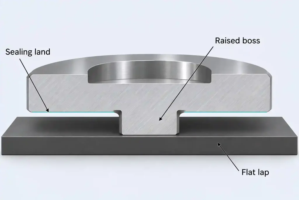
That geometry cannot be resolved by specifying a finer abrasive or a longer cycle. A shaped lap, local tooling, a different machining sequence or a design change may be needed. The proposal should explain how the required face will be reached without removing material from a feature that must remain intact.
| Part geometry | Contact issue to review | What the proposed route must address |
|---|---|---|
| Exposed annular end face | The full sealing land must register against the lap | Support, stable movement and the permitted inner and outer edge condition |
| Sealing land below a raised hub or rim | The projection can prevent contact with a flat plate | Tool clearance, local access and protection of the higher feature |
| Plain ring with two opposed working faces | Both faces may be accessible to opposed plates | Carrier suitability, final thickness and face-to-face parallelism |
| Face interrupted by grooves or ports | Contact stops and resumes at each opening | Edge damage, local removal and abrasive trapped in the openings |
| Thin or flexible ring | Applied pressure can change the face shape during processing | Support and the condition in which the released part will be measured |
Define the actual sealing land on the drawing. Do not leave the supplier to decide whether an adjacent relief, chamfer or recessed area belongs to the same requirement. Edge rounding can reduce the usable land even when the central area looks uniform.
Keep Face Flatness Separate from Ring Geometry
Flatness describes the form of an individual face. It does not locate that face relative to a bore axis, rear shoulder or mounting surface.
A ring can have two individually flat faces that are not parallel. It can also have a flat sealing face that is tilted relative to its locating bore. If those relationships matter, specify and inspect them separately. A free-running single-sided lapping operation should not be assumed to establish a bore-related orientation merely because it improves the face.
For a simple ring or spacer with two accessible opposed faces, double-sided lapping is a route to evaluate. The part is carried between upper and lower working plates, allowing both faces to be processed in one arrangement. The equipment, carrier and starting geometry still have to suit the required thickness and parallelism. A stepped body with a projecting hub may not fit that arrangement.
Processing the two faces separately is another possibility, but “both faces lapped” does not by itself demonstrate their relationship. The supplier needs a method to control and verify it.
Material removal also changes axial dimensions. Lapping a sealing face reduces its distance from an untouched rear shoulder. If a groove bottom remains untouched, the groove becomes shallower relative to the lowered face. Dimensions that start at the lapped surface therefore need acceptance limits for the finished condition.
Before releasing the CNC pre-machining dimensions, agree on the stock available for lapping. Consider the incoming face shape and defects as well as the nominal height. Removing a deep scratch may consume more stock than correcting the surrounding surface. Further lapping cannot restore a ring that has already become too short.
Match the Abrasive System to the Surface
The material and its condition influence the choice of lap plate, abrasive and carrier liquid. Particle size, pressure and slurry behavior also affect removal and texture. A grit designation alone cannot guarantee a particular Ra value.
Lapmaster Wolters’ explanation of lapping describes these interacting process variables. Its equipment-specific settings should not be copied into a universal drawing requirement.
Plate condition matters throughout the batch. The plate itself wears, so its shape needs monitoring and conditioning for the intended work. A worn or incorrectly conditioned plate can transfer an unwanted form to the parts. Increasing the cycle time is not a substitute for controlling that condition.
Lapped surfaces are not necessarily mirror-bright. Conventional abrasive systems can leave a matte appearance, while suitable diamond systems can produce reflective seal faces. Appearance alone is therefore a poor way to decide whether a part was lapped correctly.
If the requirement is mainly a bright cosmetic surface, review the mirror polishing process instead of assuming that flat lapping is needed. Conversely, a polishing operation that produces gloss does not automatically establish the required face flatness.
Lapping and honing also describe different tasks in this context. Conventional rigid bore honing uses abrasive stones inside a pre-machined hole to control size, selected form errors and texture. It is not interchangeable with finishing an external annular face against a lap. Our honing process guide covers that bore-specific decision.
For purchasing, compare routes against the same finished requirements. A quote for one accessible face is not equivalent to a quote covering two-face geometry, groove-edge control and optical inspection. Specialized carriers, incoming stock condition and cleaning access can affect the work included.
Read Surface Form from the Light Bands
An optical flat and monochromatic light can reveal the form of a suitably reflective face. The interference pattern relates to the gap between the reference flat and the workpiece.
A tilted reference over a flat surface can produce several straight, parallel, evenly spaced bands. Their presence does not mean that the face contains the same number of steps or waves.
A larger number of straight bands is not, by itself, evidence of a less flat face.
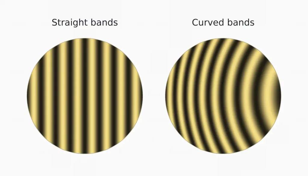
The pattern must be interpreted using the reference arrangement and the changes in the bands. Bends in the bands or local changes in their spacing can reveal surface-form variation, including near an edge. A band-based requirement also needs the light source or wavelength and the agreed interpretation method.
Kemet’s guidance on reading light bands illustrates these distinctions. Do not convert a general illustration into an acceptance limit for a different part.
The surfaces must be clean, dry and sufficiently reflective for a useful reading. The reference flat needs suitable accuracy and condition. Support and contact must not distort a thin ring. If the finish does not permit a clear optical reading, agree on a suitable alternative measurement method or a controlled preparation step before quoting.
An optical-flat result concerns the inspected face. It does not establish the ring’s thickness, its orientation to the bore, its roughness or the leakage of the assembled seal. Specify the inspected area, including any permitted edge exclusion, rather than accepting a photograph of a small central region as evidence for the entire land.
Release a Clean Face in Its Final Condition
Lapping leaves abrasive and carrier residue that must be removed appropriately. Grooves, ports and recesses need particular attention. A clean-looking face does not establish that connected passages are free of retained compound.
Choose the cleaning method for the material, geometry and required cleanliness. Protect the finished land during handling and packaging so that neighboring parts or packaging debris cannot scratch it. Any preservative must also suit the intended service and acceptance condition.
Check final dimensions and surface requirements after the agreed finishing and cleaning operations. For a flexible part, state whether acceptance applies in the free state or under defined restraint. Keep that measurement condition distinct from the load used during lapping.
If sealing performance is part of acceptance, agree on the assembly test separately: mating component, medium, pressure, temperature, duration and permitted leakage. A face-flatness report cannot replace that functional test.
For a quotation review, mark the sealing annulus and show the nearby hub, shoulder, grooves and locating bore. Include the incoming condition, permitted material removal, final axial dimensions and required face relationships. Identify whether acceptance needs optical-flat evidence, surface-texture measurements, cleanliness checks or an assembly test.
Through our precision machining services, RapidEfficient can review the CNC preparation and coordinate a proposed finishing and inspection route. Specialist lapping and measurement scope should be confirmed for the actual part before quotation.