
A cooling hole can be straightforward to drill and still be poorly placed for a hot-work insert. The steel left between that hole and the working cavity must serve the thermal design and remain suitable for the planned machining and heat-treatment route. A quotation that confirms only “H13” and a final hardness leaves those decisions open.
H13 tool steel is a chromium-molybdenum-vanadium hot-work grade used in tooling exposed to heat and mechanical loading. For a CNC-machined insert, the useful purchasing question is which steel product, internal geometry and manufacturing sequence suit the actual duty. A cooled die-casting insert provides a practical example; its operating conditions should not be transferred unchanged to forging or extrusion tooling.
Start with the Temperature Cycle at the Working Face
In die casting, repeated heating and cooling can produce thermal fatigue, often visible as a network of surface cracks called heat checking. Exposure to heat can also soften the steel and reduce its ability to carry load. These are different concerns from simply reaching a specified hardness before the insert enters service.
Uddeholm’s die-casting guide connects tool performance with the temperature cycle, steel properties and local stress concentrations. It does not reduce material selection to one room-temperature hardness reading.
For an insert review, identify the process and casting alloy, then describe how the working face is heated and cooled. Include the intended preheating practice, contact time, cycle interruptions and cooling arrangement where these are known. Distinguish measured insert temperatures from machine settings or the temperature of the incoming metal.
If the project replaces an existing insert, mark where damage first appeared. A crack network around a cavity corner, loss of shape at a thin projection and damage beside an incoming metal stream warrant different investigations. Photographs and operating history can guide that review, but they do not establish a failure mechanism by themselves.
This also explains why “maximum working temperature of H13” is an incomplete purchasing question. The temperature, exposure time, load and acceptable change in the insert must be considered together.
Specify the Steel Product Behind the H13 Name
An H13 designation does not, by itself, specify a remelting route or the complete quality requirements for a particular block.
For example, BÖHLER’s W302 product information distinguishes an air-melted product from a remelted version intended to improve cleanliness, homogeneity and toughness. The purchasing lesson is to identify the required steel quality explicitly. It is not a universal requirement to buy the most expensive available product.
Where the tooling specification requires electroslag remelting, an approved producer product, cleanliness limits or a particular inspection class, carry those requirements into the material order. If an alternative is proposed, review it before cutting the blank. A matching grade label alone does not establish compliance with the additional requirements.
Likewise, a supplier’s cross-reference between H13, 1.2344 and SKD61 is a starting point for checking the applicable specifications. It should not silently replace the material standard and acceptance requirements stated on the drawing.
Keep the stock identity connected to the insert through machining. Our guide to material certification explains why the certificate must correspond to the supplied material. For this application, ask which ordered requirements the certificate actually reports and whether any separate test evidence is required. Do not assume that a document headed “material certificate” verifies every property relevant to hot-work service.
Review the Steel Between the Cavity and the Cooling Channels
A cooling-channel layout needs more than a drilling-access check. Channel placement influences the temperature distribution around the cavity; holes and abrupt geometry changes also affect local stress. A drill diameter and an external view cannot describe all of those relationships.
Use sections through the working cavity and the complete cooling circuit to review the following features.
| Feature in the insert | What the section should make visible | Decision needed before machining |
|---|---|---|
| Cooling bore beneath the cavity | The remaining steel between the finished cavity and the bore, including local changes in cavity depth | Confirm the approved channel position and remaining wall; assess proposed changes with the tool designer |
| Channel near a cavity corner or thin projection | The relationship between the bore, corner radius and nearby surfaces | Review cooling needs and local geometry together rather than moving the hole only to simplify drilling |
| Cross-drilled passage | Hole intersections, drill-point extensions and the intended connection between passages | Define how the intersection will be made, cleaned and checked |
| Drilled access opening requiring closure | The opening, plug seat and any feature used to retain or seal the closure | Agree the closure design, installation stage and required leak or flow checks |
| Cavity located from an external seating face | The relationship between the working surface, cooling circuit and final assembly datums | Establish which references remain available after hardening and final finishing |
The table identifies review points; it does not supply a minimum wall thickness or an approved cooling layout. Those depend on the insert design and duty.
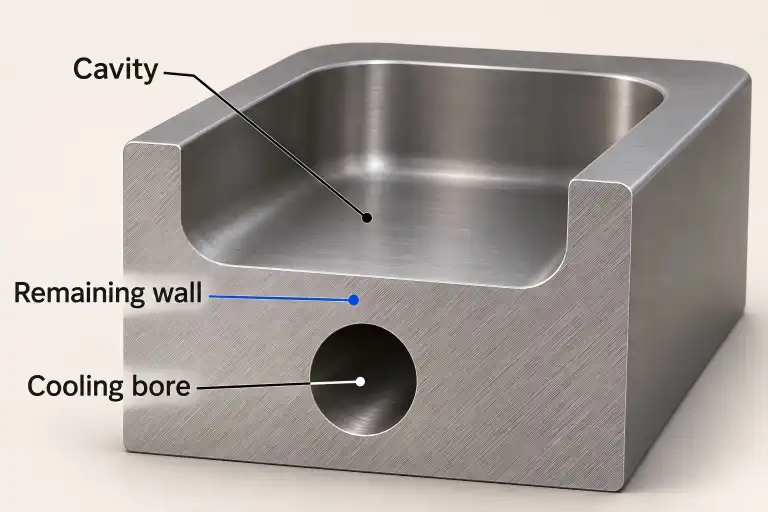
Consider a design revision that deepens the cavity toward an existing straight cooling bore beneath the cavity floor. Deepening the cavity reduces the remaining wall even if the cooling-hole drawing is unchanged. Moving the bore to restore that wall can affect its connection to another passage or the surrounding assembly. The revised cavity and cooling circuit therefore need to be reviewed together.
Inspection must follow the feature being checked. An accessible bore entrance does not establish the geometry or cleanliness of an internal intersection. A leak check addresses containment under the agreed test conditions; it does not, by itself, prove that every passage has the required flow. Before closing the channels, agree who will perform each check. Distinguish checks that require access to the intersections from any leak or flow checks required after the specified closures are installed.
Plan Hardening Around the Cavity and Channel Geometry
H13 can be rough-machined in a soft-annealed condition and then hardened and tempered before final finishing. The quotation should identify the purchased condition and the condition in which the insert will be delivered.
For a cooled insert, divide the drawing into features that must be produced before hardening and features that can be finished afterward. A cavity may remain accessible to milling or EDM, while an internal passage may offer little opportunity for later correction. Establish that access before assigning stock allowance.
Uddeholm’s Orvar Supreme data sheet includes stress relief after rough machining and discusses the balance between quench rate, distortion and cracking. Its recommendations concern that named steel product. The heat treater must assess the actual steel, section sizes and geometry rather than copy a small test specimen’s treatment or dimensional-change result.
There are two different cooling decisions here. During hardening, quenching must produce the required material condition while controlling distortion and cracking. During production, the cooling circuit manages the insert’s operating temperature cycle. Advice about one stage does not automatically apply to the other.
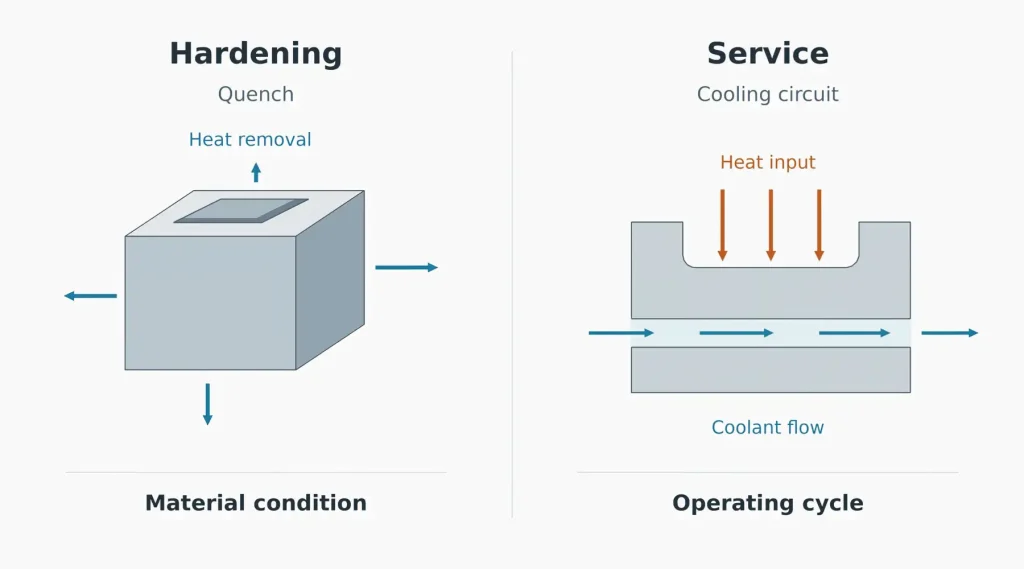
The machining plan should therefore name the cavity surfaces, seating faces and critical bores that will be checked or corrected after treatment. An allowance on an accessible outside face does not provide a correction method for a misplaced internal cooling passage.
If EDM forms part of the final cavity, include any specified surface-layer removal and its effect on the cavity dimensions. The EDM recast-layer guide addresses the evidence needed for that separate requirement. Reaching the cavity size and reaching the required surface condition must both fit within the planned route.
For a CNC machining review, send the insert model with cavity and cooling-circuit sections, the required H13 specification, delivery condition and known operating cycle. For a replacement insert, add the damage locations and relevant service history. The proposal should identify the material supply, heat-treatment responsibility, inaccessible features and the inspection sequence for the cooling passages. Specialized tooling, heat-treatment and internal-channel inspection scope should be confirmed for the actual project before quotation.