
Before ordering surface grinding for a thin plate, agree how it will be held and how it will be measured after release. A magnetic chuck can pull a bowed steel blank toward its own flat surface. Grinding the exposed face in that condition does not establish the shape of the released part.
The purchasing decision is whether the proposed holding arrangement, stock allowance and grinding sequence can deliver the specified plate. A quote that includes only a ground finish leaves the support and acceptance conditions unresolved.
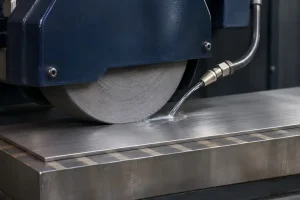
Surface grinding removes material with a rotating abrasive wheel. In a common horizontal-spindle arrangement, the wheel’s periphery cuts the face as the work moves beneath it. The discussion here concerns broad faces on thin CNC-machined plates and covers, especially ferromagnetic steel parts held on a magnetic chuck.
The Holding Face Is Part of the Grinding Plan
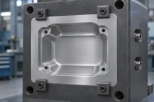
Review the underside as carefully as the face to be ground. Pockets, slots, raised pads and existing bow can change which areas actually contact the chuck.
A magnetic chuck needs a suitable magnetic path through the workpiece. Material type, thickness, contact area and air gaps affect the available holding force. Pole pitch—the spacing of the chuck’s poles—also matters when matching a chuck to a thin or narrow part.
Eclipse Magnetics’ chuck-selection guide explains these factors. A fine-pole design may suit small or thin workpieces, but the label alone does not establish adequate holding for a particular plate and grinding operation.
| Plate underside or section | Magnetic-contact issue | What the proposed setup must resolve |
|---|---|---|
| Broad, continuous steel underside | Contact depends on actual seating, surface condition and material response | Clean seating and suitable contact across the chuck’s poles |
| Narrow steel strip | Its position may provide an unsuitable magnetic path across the pole pattern | Part orientation and a pole arrangement suited to the strip |
| Pockets leaving thin floors and narrow lands | The outer footprint overstates the solid area available for contact | Support beneath flexible regions and holding through the remaining material |
| Bowed blank with gaps underneath | Contact changes as the chuck pulls the plate down | How much the setup changes the part’s shape before cutting |
| Aluminum plate or another material unsuitable for direct magnetic holding | The workpiece does not provide the required magnetic path | A separate fixture or another holding method suited to the grinding load |
The table identifies review questions, not an approved fixture design. A carrier held magnetically still needs a separate means of securing a nonmagnetic workpiece. A vacuum fixture or mechanical clamp can also bend a flexible plate.
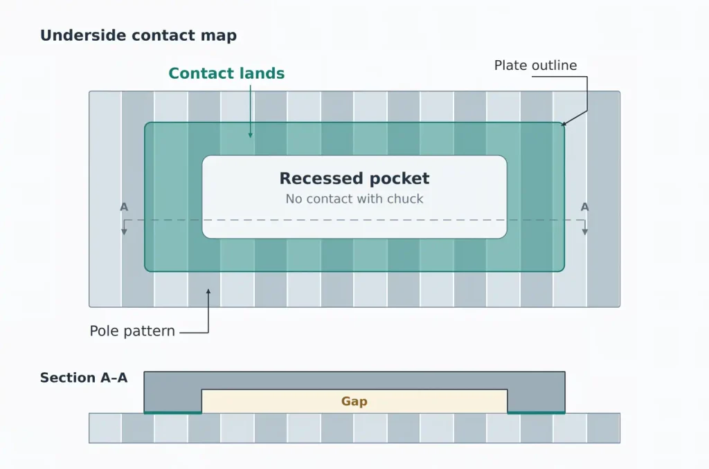
Ask the supplier to show the actual support and holding arrangement, including any stops needed to resist grinding forces. Reducing magnetic force to limit bending also reduces the available hold. It should be evaluated within a secure setup, not treated as a general instruction to turn down the chuck.
Burrs, trapped chips and damaged seating areas can create local high spots. Clean contact matters both when grinding the first face and when turning the part over. A particle left beneath a thin plate can change its supported shape.
Separate Chuck Pull-Down from Permanent Shape Change
Consider a bowed steel plate that bends elastically when the magnetic chuck is engaged. While held, the wheel removes material from the exposed face. When the holding force is removed, elastic recovery can change that newly ground face.
This explains why a flat reading while the chuck is on can coexist with a bowed released part. It does not prove that every post-grinding distortion comes from magnetic pull-down.
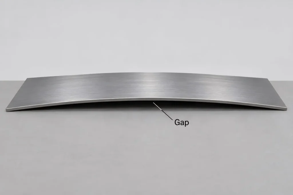
A useful setup check compares the plate’s shape before and after engaging the hold, without cutting. Use a controlled measurement arrangement that accounts for rigid-body movement and support changes. If the plate changes shape at this stage, the holding arrangement is already influencing the geometry that will be ground.
Material removal introduces another problem. Removing a layer can redistribute residual stress in the blank. Thermal processing and earlier machining also affect the incoming condition. Turning the chuck off does not reverse a permanent change caused by the manufacturing route.
Specify the material’s delivered condition and relevant prior processing, rather than just its grade and nominal thickness. Our comparison of hot-rolled and cold-rolled machining stock explains why stock condition and usable material need separate review.
The supplier may propose staged removal from opposing faces, intermediate release checks, different support or an appropriate treatment before final grinding. These options require a part-specific plan. Alternating faces is not proof that all residual stress has been removed, and leaving a part on a bench is not a defined stress-relief treatment.
Stock allowance must cover the actual shape and surface condition to be corrected. Nominal blank thickness minus finished thickness does not establish how much can be removed at every location. A bowed plate may need uneven removal to create the required faces, while pockets or a minimum-thickness limit restrict that correction.
Agree on a point at which the route must be reconsidered. If further grinding would violate the minimum thickness or damage an existing feature, another finishing pass is not an acceptable recovery plan.
Check Whether the Wheel Is Cutting or Rubbing
Even with suitable support, grinding can introduce heat and forces that affect a thin plate.
A wheel that is not cutting freely can rub the surface and generate heat. Wheel selection, dressing, coolant delivery and the contact conditions therefore belong in the process review. Dressing renews the wheel’s working surface; changing grit size alone does not resolve every grinding problem.
Norton’s surface-grinding guidance describes how abrasive behavior, dressing and cooling affect cutting and heat generation. Its recommendations depend on the grinding system and should not be converted into one universal wheel specification or finishing depth.
A smaller infeed is not automatically a cooler cut if the wheel continues rubbing. Likewise, a longer spark-out—the finishing portion with no additional commanded infeed—cannot correct a holding arrangement that bends the plate.
A temperature difference through the section can temporarily bow a thin part. Excessive grinding heat can also damage the material, depending on its alloy and condition. Temporary thermal movement and permanent surface damage require different checks.
For a hardened functional face, agree whether acceptance includes checks for grinding damage and which method applies. A smooth appearance or an acceptable roughness reading does not establish the underlying material condition. Do not infer a defect solely from color, or approve the surface solely because discoloration is absent.
Approve the Released Part Before Repeating the Setup
For a new, distortion-sensitive route, agree what the first-piece review must establish before repeating the setup across the batch.
The report should identify the ground face, evaluated area, final thickness, support locations, restraint condition and temperature condition. Where both faces matter, include their required relationship. A small set of thickness readings cannot establish complete face flatness.
Free-state acceptance still requires suitable support during measurement. Gravity, contact forces and support positions can affect a flexible plate. If acceptance instead applies under specified restraint, define that restraint explicitly. The grinding chuck is not automatically an equivalent substitute for the installed assembly.
Keep form and orientation separate in the inspection plan. Our flatness-versus-parallelism guide explains why a face-flatness result does not establish its relationship to the opposite datum face.
Compare measurements made in the agreed condition after release and suitable temperature stabilization. For a disputed result, retain the support arrangement and measured surface data, not just a single pass/fail value. A passing first-piece report provides evidence for the inspected part and the proposed route. It does not replace the agreed checks on later production.
Quotes should cover the same work: underside preparation, any dedicated holding arrangement, intermediate release checks, final grinding, and the required inspection. These operations can explain a price difference that is invisible in a simple “surface ground” line item.
For a precision-machining review, provide both faces of the plate, underside pockets and lands, incoming material condition, remaining stock and the required measurement state. RapidEfficient can review the CNC preparation and coordinate a proposed grinding and inspection route. Specialist workholding and surface-integrity checks should be confirmed for the actual part before quotation.