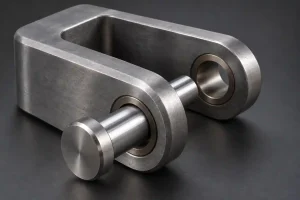
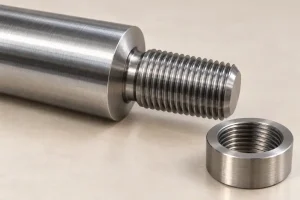
CNC machining tolerance stack-up is the combined effect of dimensional variation across several features, datums, setups, fixtures, and inspection references.
A single bore, hole, or mounting face may meet its individual tolerance while the finished part still fails assembly. This happens when the relationships between those features move beyond the functional limit.
For a simple one-dimensional tolerance chain, two common calculation methods are used:
- Worst-case analysis: Adds the absolute contribution of every tolerance and assumes that all dimensions reach their least favorable limits at the same time.
- Root sum square analysis: Combines statistically independent variation using the square root of the sum of the squared tolerance contributions.
The calculation method is only part of the review. Datum selection, workholding, clamping deformation, thermal movement, residual-stress release, tool wear, setup transfer, and inspection alignment can all change the final result.
A useful tolerance stack-up review therefore connects the drawing, machining sequence, fixture strategy, process capability, and inspection plan before production begins.
Where CNC Tolerance Stack-Up Starts
| Stack-Up Source | How It Creates Error | Practical Control Method |
|---|---|---|
| Weak datum selection | Features are measured from a reference that does not match the functional datum | Use functional datums and verify datum repeatability |
| Fixture movement | Part position changes between roughing, finishing, or repeated setups | Use custom fixtures, soft jaws, or vacuum fixtures |
| Clamping deformation | Thin walls bend under pressure | Reduce clamping force and use balanced support |
| Thermal expansion | Heat changes part size during cutting | Control coolant, toolpath, and cutting sequence |
| Tool wear | Feature size gradually drifts during production | Monitor tool life and inspect critical features |
| Multiple setups | Each setup adds alignment error | Use common datums, probing, dowel pins, and CMM verification |
| Inspection mismatch | Inspection reference does not match the drawing datum structure | Align CMM inspection with GD&T datum structure |
What Is Tolerance Stack-Up in CNC Machining?
Tolerance stack-up is the accumulation of small dimensional variations across a part, assembly, or machining process.
In CNC machining, each feature may appear to be within tolerance individually. But when multiple features depend on each other, the combined error can exceed the functional requirement.
The following values are illustrative only. Actual tolerances must be based on the assembly function, material, geometry, manufacturing process, process capability, datum structure, and inspection plan.
For example, a housing may have:
- A bearing bore tolerance of ±0.005 mm
- A bolt hole position tolerance of ±0.02 mm
- A sealing face flatness requirement of 0.01 mm
- A concentricity requirement between two machined features
Each tolerance may look manageable on the drawing. But if the datum is unstable, the fixture shifts, or the part deforms after roughing, the final assembly may fail even though several individual dimensions appear acceptable.
If tolerance stack-up is only discovered during final inspection, it is already too late. At that point, the part may look acceptable on individual dimensions but still fail when the bearing, bolt pattern, and mating face are checked together.
This is why tolerance stack-up should be reviewed before machining begins, not only checked after the part is finished.
How to Calculate CNC Tolerance Stack-Up
The correct calculation depends on the type of tolerance chain.
A simple linear dimension chain can often be reviewed using worst-case or root sum square analysis. More complex relationships involving position, angle, runout, datum mobility, material-boundary conditions, or three-dimensional geometry may require a more detailed GD&T analysis, coordinate model, or tolerance simulation.
Worst-Case Tolerance Stack-Up
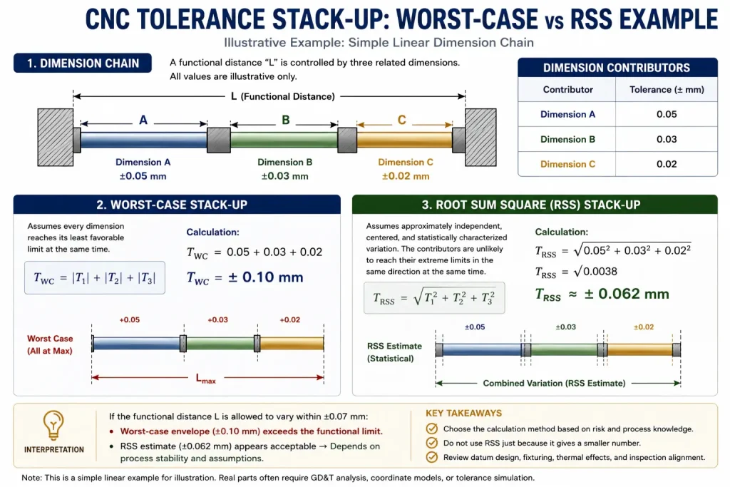
For a simple one-dimensional chain, the worst-case tolerance is calculated by adding the absolute contribution of each tolerance:
TWC = |T₁| + |T₂| + … + |Tₙ|
Here, each T represents the plus-or-minus tolerance contribution, not the full width of the tolerance zone.
Worst-case analysis assumes that every contributing dimension reaches its least favorable limit at the same time. It is conservative, but it provides a clear envelope of possible variation.
It is commonly considered when:
- Assembly failure cannot be accepted
- Components must remain interchangeable
- The production process is not yet statistically characterized
- The number of contributing dimensions is limited
- A safety-critical or function-critical interface is being reviewed
- The consequences of an out-of-limit condition are significant
Root Sum Square Tolerance Stack-Up
For a simple linear chain with approximately independent sources of variation, the RSS result is:
TRSS = √(T₁² + T₂² + … + Tₙ²)
RSS usually produces a smaller result because it assumes that all contributing dimensions are unlikely to reach their extreme limits in the same direction at the same time.
However, RSS should not be selected only because it produces a more convenient number.
Before using a statistical result, review whether:
- The manufacturing processes are stable
- The dimensions are reasonably centered
- The tolerance contributors are sufficiently independent
- Suitable process data are available
- Systematic offsets have been separated from random variation
- The accepted failure probability matches the application risk
A fixture offset, incorrect tool compensation, common datum error, or temperature bias may affect several features in the same direction. These correlated or systematic errors should not automatically be treated as independent RSS contributors.
Numerical Example
Assume a simple linear assembly chain contains three independent dimensional contributions:
- Dimension A: ±0.05 mm
- Dimension B: ±0.03 mm
- Dimension C: ±0.02 mm
Worst-Case Calculation
TWC = 0.05 + 0.03 + 0.02
TWC = ±0.10 mm
RSS Calculation
TRSS = √(0.05² + 0.03² + 0.02²)
TRSS = √0.0038
TRSS ≈ ±0.062 mm
If the assembly allows no more than ±0.07 mm of total variation:
- The RSS result appears to fit within the functional limit.
- The worst-case result exceeds the functional limit.
This does not mean RSS is automatically the correct answer. The engineering team must decide whether the process stability, dimensional distributions, independence assumptions, and consequences of assembly failure support a statistical calculation.
Do Not Add Every Drawing Tolerance Into One Formula
Only tolerances that contribute to the same functional relationship belong in the chain.
For each contributor, identify:
- The start and end points of the functional dimension
- Whether the dimension increases or reduces the final gap
- The controlling datum reference
- Whether the variation is dimensional, geometric, thermal, or setup-related
- Whether the contributor is independent, correlated, or systematic
- Whether bonus tolerance or material-boundary conditions apply
- Whether the part is measured freely or in a restrained condition
A tolerance stack should represent a specific function, such as a clearance, alignment, sealing condition, bearing location, or assembly gap. It should not be created by collecting every tolerance shown on the drawing.
For broader tolerance allocation and drawing review principles, see our CNC machining tolerances guide.
Why Small CNC Errors Become Expensive Scrap
Precision parts rarely fail because of one obvious mistake. More often, they fail because several small deviations happen at the same time.
A typical chain looks like this:
- The drawing defines a functional datum.
- The machinist chooses a different physical datum for easier setup.
- The fixture clamps a thin wall too aggressively.
- Roughing releases internal material stress.
- Finishing removes material from a slightly distorted part.
- CMM inspection shows that the final feature is out of true position.
No single step looks catastrophic. But together, they create a tolerance stack-up problem.
In real production, tolerance stack-up rarely announces itself early. The part may pass a quick caliper check, the bore diameter may look correct, and the surface finish may meet the drawing. The problem appears later, when the part is assembled and the bolt pattern, bearing bore, and mating face no longer agree with each other.
This is why experienced machinists do not treat tolerance stack-up as a math problem only. It is a setup problem, a fixture problem, a heat problem, and finally an inspection problem.
This is especially common in:
- Thin-wall aluminum housings
- Motor housings
- Optical mounts
- Semiconductor bushings
- Heat sinks
- Precision fixture components
The Datum Problem: Design Datum vs Machining Datum
One of the biggest causes of tolerance stack-up is the gap between the design datum and the machining datum.
A design datum is created by the engineer to define functional relationships. A machining datum is the physical reference used in the shop to locate the part. If these two are not aligned, tolerance stack-up becomes much harder to control.
| Datum Type | Who Defines It? | Main Purpose | Stack-Up Risk |
|---|---|---|---|
| Design Datum | Engineer / designer | Controls function and GD&T intent | May be difficult to access physically |
| Machining Datum | CNC machinist / process engineer | Locates the part during machining | May not match final assembly function |
| Inspection Datum | QC / CMM engineer | Verifies part against drawing | Can produce misleading results if not aligned |
| Functional Datum | Final assembly requirement | Ensures real-world fit | Often ignored too late in production |
Engineer’s Note
The largest or easiest surface is not automatically the most reliable datum feature.
A broad surface may still be unsuitable when it is bowed, flexible, rough, unfinished, contaminated, or inconsistent between parts. If the primary datum feature rocks or deforms during probing and clamping, downstream features may inherit the resulting setup error.
Before machining, identify:
Which feature relationships control the final function and assembly of the part?
The drawing datum structure, fixture contact, machining references, setup transfers, and inspection alignment should protect those relationships.
For practical datum-selection principles, see our types of CNC machining datums guide.
How Fixtures Influence Tolerance Stack-Up
Fixtures are not just workholding tools. They are part of the tolerance system.
A fixture can reduce error, or it can create error.
For example, if a thin-wall aluminum component is clamped with too much force, it may appear stable during machining. But once the clamp is released, the part springs back and the final dimensions shift. This is a common cause of tolerance failure in thin-wall CNC machining.
A common mistake is assuming that a rigid clamp always improves accuracy. In thin-wall machining, excessive rigidity can create a false sense of stability during cutting, only for the part to spring back after release.
Fixture-Related Stack-Up Risks
| Fixture Issue | Result | Better Approach |
|---|---|---|
| Over-clamping | Thin-wall deformation | Use soft jaws or low-pressure clamping |
| Poor support | Vibration and surface chatter | Add custom support points |
| Unstable locating pins | Position repeatability loss | Use hardened dowel pins or precision locators |
| Fixture thermal growth | Dimensional drift | Control machining temperature |
| Poor access for probing | Datum inconsistency | Design probe-accessible reference points |
For more details on deformation control, see:
How to Reduce the Deformation During CNC Machining
Thermal Expansion: The Hidden Stack-Up Factor
Thermal expansion is often underestimated in CNC tolerance stack-up.
During machining, temperature rise may be influenced by:
- Tool–workpiece friction
- Cutting speed and tool engagement
- Poor chip evacuation
- Insufficient or inconsistent cooling
- Long machining cycles
- Heat retained in the workpiece, tool, spindle, or fixture
Residual-stress release is a separate source of dimensional movement. Heavy or unbalanced stock removal can allow the part to distort even when cutting temperature is reasonably controlled.
Even if the CNC machine is accurate, the part itself may expand during cutting. Once it cools, the final dimension may change.
This matters especially for:
- Aluminum parts
- Thin-wall components
- Long parts
- High-speed machining
- Precision bores
- Tight sealing faces
For bearing bores, sealing faces, and bolt patterns, thermal drift can turn a small setup error into an assembly-level failure.
For precision aluminum components, thermal control should be combined with an appropriate roughing strategy and sufficient finishing allowance. Otherwise, a part may measure correctly while warm but move outside the required condition after cooling.
Rough, Stabilize, Recheck, and Finish
Parts with heavy stock removal, thin walls, asymmetric geometry, or meaningful residual-stress risk may require a staged machining sequence.
A possible process is:
- Rough machine the major geometry while leaving suitable finishing allowance.
- Remove the part or reduce the clamping load when the process requires a free-state check.
- Allow the component to stabilize according to the material, geometry, removed volume, and production plan.
- Reinspect or re-establish the relevant datum features.
- Correct the workholding or machining reference when movement is detected.
- Finish the assembly-critical dimensions and geometric relationships.
- Verify the completed part in the specified inspection condition.
This approach may be useful for:
- Thin-wall housings
- Parts machined from plate with substantial stock removal
- Long or asymmetric components
- Precision mounting structures
- Bearing and seal housings
- Optical or sensor supports
- Fixture plates with related holes and surfaces
It is not a universal sequence for every tight-tolerance component.
Some parts can be rough-machined and finished efficiently in one controlled setup. Others may need intermediate stress relief, thermal stabilization, fixture changes, datum transfer, or additional verification.
Engineer’s Note
The process should not use an arbitrary waiting period as a substitute for understanding the material and geometry.
The required sequence depends on:
- Alloy and material condition
- Stock form
- Residual-stress risk
- Percentage and balance of stock removal
- Wall thickness
- Part rigidity
- Fixture restraint
- Temperature condition
- Required feature relationships
- Production volume
The purpose is to finish critical features from a stable and repeatable reference—not simply to add more process steps.
CMM Inspection: Verifying the Tolerance Chain
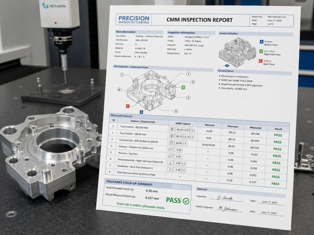
CMM inspection can verify whether the completed part satisfies the applicable dimensional and geometric relationships defined by the drawing.
Depending on the drawing and functional requirements, the inspection plan may evaluate:
- Critical dimensions
- Applicable flatness controls
- Applicable parallelism and perpendicularity controls
- Bore or axis relationships
- Position tolerances
- Applicable runout controls
- Datum reference frame alignment
- First-article or requested production-inspection results
Only the controls that apply to the drawing and assembly should be included. The inspection alignment must reproduce the required datum reference frame rather than relying on an unrelated edge, convenient coordinate system, or uncontrolled best-fit alignment.
CMM inspection can identify whether the final part meets the defined requirements, but it cannot repair an unstable fixture, incorrect datum strategy, distorted component, or unsuitable machining sequence after production is complete.
For buyer-side report review, see our guide to CMM inspection for CNC machined parts.
Tolerance Stack-Up Example: Bearing Bore and Bolt Pattern
Consider a CNC machined aluminum housing with a precision bearing bore and a bolt hole pattern.
The drawing may require:
- Bearing bore diameter: tight tolerance requirement
- Bore concentricity: controlled by the drawing requirement
- Bolt hole true position: controlled by the drawing requirement
- Mounting face flatness: controlled by the drawing requirement
If the mounting face is used as the primary datum but it is not flat enough after roughing, the bore position may shift. If the bolt pattern is machined in a second setup with a different datum, the true position error increases further.
The final result may be:
- Bore diameter is acceptable
- Bolt holes are individually acceptable
- Mounting face is acceptable
- But the assembly still fails because the relationship between features is wrong
This is tolerance stack-up.
This example involves positional and geometric relationships rather than only a simple linear dimension chain. Bore location, bolt-hole position, face flatness, and datum alignment should not automatically be combined by adding their printed tolerance values.
Depending on the drawing, the analysis may require datum-based GD&T interpretation, assembly simulation, coordinate analysis, or a dedicated tolerance model.
For this type of part, the machining plan should not start with the easiest clamping surface. It should start with the feature relationship that matters most in assembly.
How to Reduce CNC Machining Tolerance Stack-Up
1. Start With Functional Datum Planning
Before machining, identify which feature matters most in the final assembly. This could be a bearing bore, sealing face, locating hole, or mating surface.
The machining strategy should protect that feature relationship.
2. Use Stable Fixtures
Fixtures should support the part without distorting it. For thin-wall parts, soft jaws, vacuum fixtures, and custom supports can reduce clamping-related stack-up.
3. Control Roughing Stress
Heavy roughing can release residual stress. Use balanced roughing and leave finishing allowance for critical features.
4. Manage Heat
Use proper coolant, cutting parameters, and machining sequence to prevent thermal drift.
5. Verify With CMM Inspection
Critical features should be checked against the correct datum reference frame, not just measured as isolated dimensions.
6. Review Tolerance Feasibility During DFM
If the drawing requires tight tolerance across multiple setups, DFM review should be done before quotation and production to identify datum, fixture, machining, and inspection risks.
Hidden Cost: Why Tolerance Stack-Up Increases CNC Machining Cost
Tolerance stack-up does not only increase scrap risk. It also increases cost.
| Cost Driver | Why It Happens |
|---|---|
| More setup time | Datums and fixtures require extra planning |
| Slower machining | Heat and stress must be controlled |
| More inspection | Critical dimensions require CMM checks |
| Higher fixture cost | Custom workholding may be needed |
| More rework risk | Small errors may only appear after assembly |
| Longer lead time | Stable machining requires more process control |
This is why the cheapest quote is not always the lowest real cost.
If tolerance stack-up is ignored, the buyer may pay later through rework, delayed assembly, or rejected parts.
FAQ: CNC Machining Tolerance Stack-Up
What is tolerance stack-up in CNC machining?
Tolerance stack-up is the combined variation created by several dimensions, geometric controls, datums, setups, fixtures, thermal conditions, tools, and inspection references that affect the same functional relationship.
Individual features may meet their own tolerances while the complete part or assembly still fails because the relationship between those features exceeds the allowable limit.
How do you calculate a tolerance stack-up?
For a simple linear chain, worst-case analysis adds the absolute value of each tolerance contribution:
TWC = |T₁| + |T₂| + … + |Tₙ|
RSS analysis combines approximately independent statistical contributors:
TRSS = √(T₁² + T₂² + … + Tₙ²)
More complex geometric relationships may require GD&T-based analysis, coordinate modeling, or tolerance-simulation software.
What is the difference between worst-case and RSS analysis?
Worst-case analysis assumes all contributors reach their least favorable limits at the same time. It provides a conservative variation envelope.
RSS assumes that suitable contributors behave statistically and are not all likely to reach their extreme values in the same direction simultaneously. It should only be used when process behavior and statistical assumptions support it.
Can geometric tolerances be added like linear dimensions?
Not automatically.
Position, flatness, perpendicularity, runout, datum shift, material-boundary conditions, and three-dimensional feature relationships may affect the assembly differently from a simple plus-or-minus dimension.
The tolerance chain must represent the actual functional relationship defined by the drawing.
Is CMM inspection enough to control tolerance stack-up?
No.
CMM inspection can verify applicable dimensions and geometric relationships, but it cannot correct poor datum planning, unstable workholding, thermal movement, part distortion, or an unsuitable machining sequence after the component has been produced.
Inspection planning should be connected to the drawing and manufacturing strategy before production.
Do tighter tolerances always improve part quality?
No.
Unnecessary tight tolerances can increase machining time, inspection requirements, fixture complexity, scrap risk, and cost without improving function.
Tolerances should be assigned according to assembly, sealing, motion, alignment, thermal behavior, interchangeability, and other functional requirements.
Final Review Before Production
CNC tolerance stack-up is not created by one number alone. It develops through the interaction of dimensions, geometric controls, datums, fixtures, machining sequence, thermal conditions, residual stress, tool behavior, setup transfer, and inspection alignment.
Worst-case and RSS calculations can help quantify a simple dimensional chain, but the calculation must represent the real functional relationship. Statistical methods also require suitable process assumptions and should not be selected only because they produce a smaller result.
Before releasing an assembly-critical CNC part, review:
- Which feature relationships control function
- Which datums establish those relationships
- How the part will be supported and clamped
- Whether stock removal may release distortion
- Which features should remain in the same setup
- How machining references will transfer between operations
- Which tolerance contributors are linear, geometric, systematic, or statistical
- How the finished part will be aligned and inspected
If a part includes tight feature relationships, multiple datum references, or assembly-critical tolerances, the drawing, machining sequence, workholding, and inspection plan should be reviewed together before production.
Rapid Efficient can review custom CNC projects according to the drawing, material, quantity, tolerance relationships, surface requirements, and requested inspection documentation.