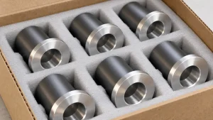
REPRESENTATIVE CASE STUDY
This representative engineering case uses simplified geometry, requirements, and process illustrations to explain tolerance control for a CNC-machined PEEK component. It does not reproduce or disclose a specific customer project.
The example focuses on an unfilled PEEK insulating housing with a critical bore, a mounting-hole pattern, a contact face, and several relatively thin sections.
The main manufacturing problem is not one unusually small tolerance. It is maintaining the required relationship between these features after stock removal, unclamping, temperature change, deburring, and final inspection.
PEEK can be machined into precise functional components, but the result depends on the exact material grade, stock form, geometry, workholding, cutting strategy, and measurement condition. Unfilled, glass-filled, carbon-filled, and wear-modified grades should not be treated as interchangeable materials.
Representative Project Overview
| Project Item | Representative Requirement |
|---|---|
| Part type | Precision insulating housing |
| Material | Unfilled PEEK; exact manufacturer and grade to be specified |
| Production stage | Prototype and low-volume production |
| Main features | Critical bore, mounting-hole pattern, contact face, thin side sections |
| Primary function | Maintain alignment while providing electrical and material separation |
| Main risks | Clamping deformation, cutting heat, movement after stock removal, burrs, inspection-condition differences |
| Inspection priority | Bore size, bore-to-datum relationship, mounting-hole position, applicable face geometry |
| Documentation | Drawing-based dimensional report; CMM report where related geometry requires it |
The specifications in this case are intentionally simplified. Actual tolerance values must be defined by the assembly, operating environment, material grade, geometry, production quantity, and inspection method.
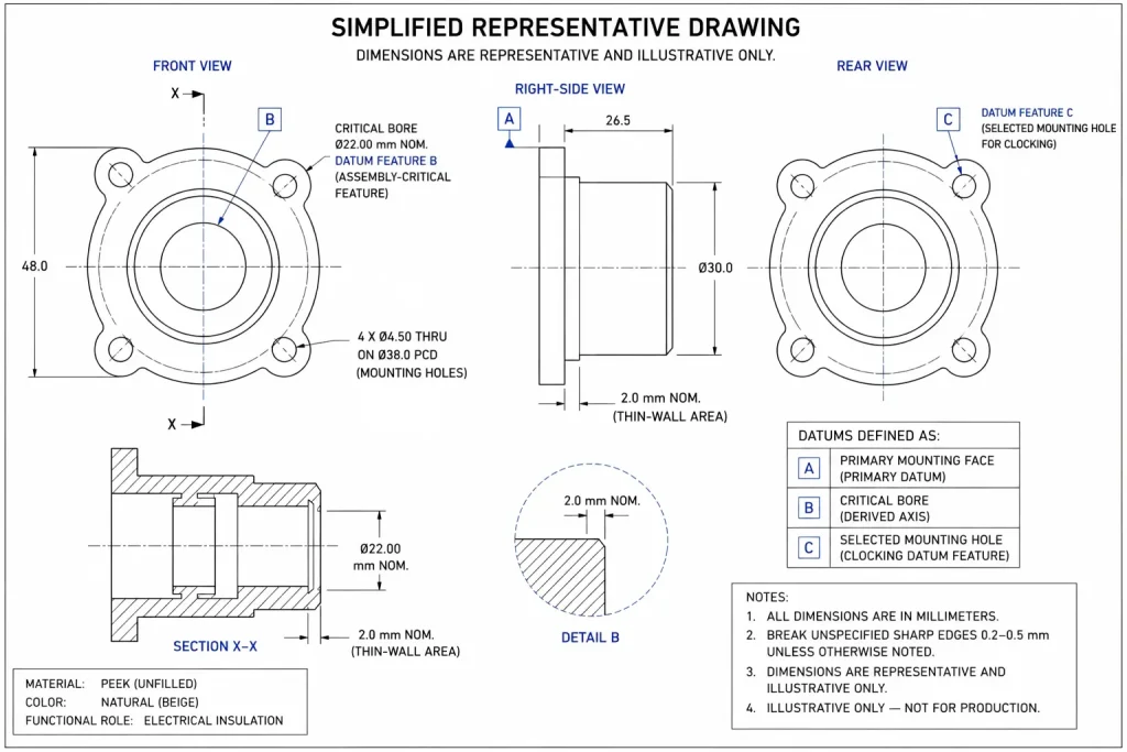
The Functional Requirement Was a Relationship, Not One Tight Number
A PEEK component can meet every isolated size dimension and still create an assembly problem.
In this representative housing, the important relationship connects:
- The primary contact face
- The critical bore axis
- The mounting-hole pattern
- The side locating feature
- The free-state shape of the housing
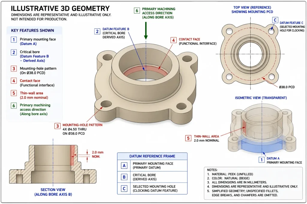
The bore cannot be evaluated only by checking its diameter. Its location and orientation relative to the mounting and contact features may be equally important.
This means the tolerance review must identify:
- Which feature establishes the primary datum
- Which features should remain related within one setup
- Whether the component is inspected freely or while restrained
- Which dimensions affect assembly
- Which tolerances can be relaxed without affecting function
- Which features require a coordinate-based inspection method
Applying very tight tolerances to every dimension would not automatically improve the component. It could increase machining time, inspection cost, and rejection risk while failing to protect the relationships that actually control assembly.
Our CNC machining tolerances guide explains why tolerance allocation should begin with function rather than a universal precision value.
The Exact PEEK Grade Had to Be Confirmed First
“PEEK” is not a complete material specification.
The RFQ and drawing should identify, where applicable:
- Material manufacturer
- Commercial grade
- Unfilled or filled condition
- Filler type and percentage
- Natural or pigmented condition
- Stock form
- Required certification or traceability
- Operating temperature
- Chemical exposure
- Electrical requirements
- Cleaning or sterilization environment
Unfilled PEEK, glass-filled PEEK, carbon-filled PEEK, and bearing-grade formulations can differ in stiffness, wear behavior, thermal response, abrasiveness, electrical properties, and machining behavior.
Stock form also matters. Extruded, compression-molded, or otherwise processed shapes may not respond identically when large amounts of material are removed. Victrex distinguishes natural, fibre-reinforced, wear-modified, temperature-enhanced, and industry-specific PEEK grades, while also noting differences associated with processing routes and material form.
This case therefore uses one material definition:
Unfilled PEEK stock from a specified and traceable grade.
A carbon-filled version of the same geometry would require a separate tool-wear, edge-quality, and inspection review.
For a broader material comparison, see our guides to PEEK vs POM for CNC machining and the best plastics for CNC machining.
Where Dimensional Drift Could Enter the Process
Clamping Deformation
PEEK is less rigid than common machining metals. Excessive jaw pressure or poorly distributed support can temporarily distort the part during machining.
A feature may be cut correctly while the component is clamped and then move after release.
The fixture plan should therefore consider:
- Contact location
- Clamping direction
- Clamping-force distribution
- Support beneath thin or open sections
- Jaw contact marks
- Free-state geometry after release
- Repeatable relocation between operations
The objective is not simply to hold the stock tightly. It is to locate it repeatably without forcing the component into a temporary shape.
Cutting Heat
PEEK does not remove cutting heat in the same way as aluminum or steel.
Heat may build near the cutting zone when:
- Tools are dull
- Engagement is excessive
- Chips remain in the cut
- Toolpaths repeatedly load one local area
- Long finishing passes are used without sufficient thermal control
- The part is inspected before reaching the required measurement condition
Heat control does not require a universal coolant system or a fixed machine-room temperature for every project.
The appropriate approach depends on the material grade, feature, cleanliness requirement, surface requirement, machine, tool, chip-removal method, and inspection plan.
Movement After Stock Removal
Removing a large or unbalanced amount of stock may allow the remaining geometry to move.
The risk increases when the part contains:
- Thin walls
- Deep internal cavities
- Strongly asymmetric geometry
- Large differences in section thickness
- Long unsupported features
- Critical dimensions spanning several machined surfaces
Staged roughing may help, but it is not a fixed formula. There is no universal requirement to remove a particular percentage of material or wait for a fixed number of hours.
The process should respond to the actual geometry and observed movement.
Tool Wear
Unfilled PEEK and fibre-filled PEEK do not create the same tooling demands.
Sharp carbide tools may be suitable for many unfilled PEEK parts. Abrasive reinforced grades may justify a different tool material, coating, cutting strategy, or replacement interval.
Tool wear can affect:
- Bore diameter
- Edge condition
- Surface texture
- Burr formation
- Feature position
- Repeatability across a batch
No tool material guarantees zero deflection or unlimited dimensional stability. Ensinger likewise distinguishes unfilled and reinforced PEEK grades and notes that the formulation affects cutting forces, heat response, and machinability.
Inspection Condition
A measurement is only meaningful when the inspection condition matches the drawing and functional requirement.
The plan should define:
- Measurement temperature or stabilization condition
- Free-state or restrained inspection
- Datum alignment
- Time between machining and final inspection where relevant
- Applicable measurement method
- Reported actual results
- Decision rule for results near a tolerance limit
A part measured immediately after machining may not be in the same condition as the component during final assembly.
Datum and Fixture Plan for the Representative Housing
The simplified housing uses three functional references:
- Datum A: Primary contact face
- Datum B: Locating side feature
- Datum C: Secondary end feature
The critical bore and mounting-hole pattern are controlled relative to this datum structure.
The fixture should reproduce the intended functional references without overconstraining the component.
A suitable starting approach may include:
- Broad, clean support beneath the primary area
- Controlled lateral location against the secondary datum feature
- A limited tertiary stop to control rotation
- Low and repeatable clamping force
- Local support beneath thin sections where required
- Clearance around surfaces that must not receive clamp marks
- A free-state check after unclamping
The exact fixture depends on the stock shape and machining sequence. Soft jaws, profiled supports, vacuum workholding, adhesive methods, modular fixtures, or custom nests may each be suitable for different PEEK geometries.
The fixture should not be selected by asking:
How can we apply the most clamping force?
It should be selected by asking:
How can we maintain repeatable location while applying the least harmful restraint?
Additional workholding principles are covered in our guide on how to reduce deformation during CNC machining.
A Staged Machining Sequence
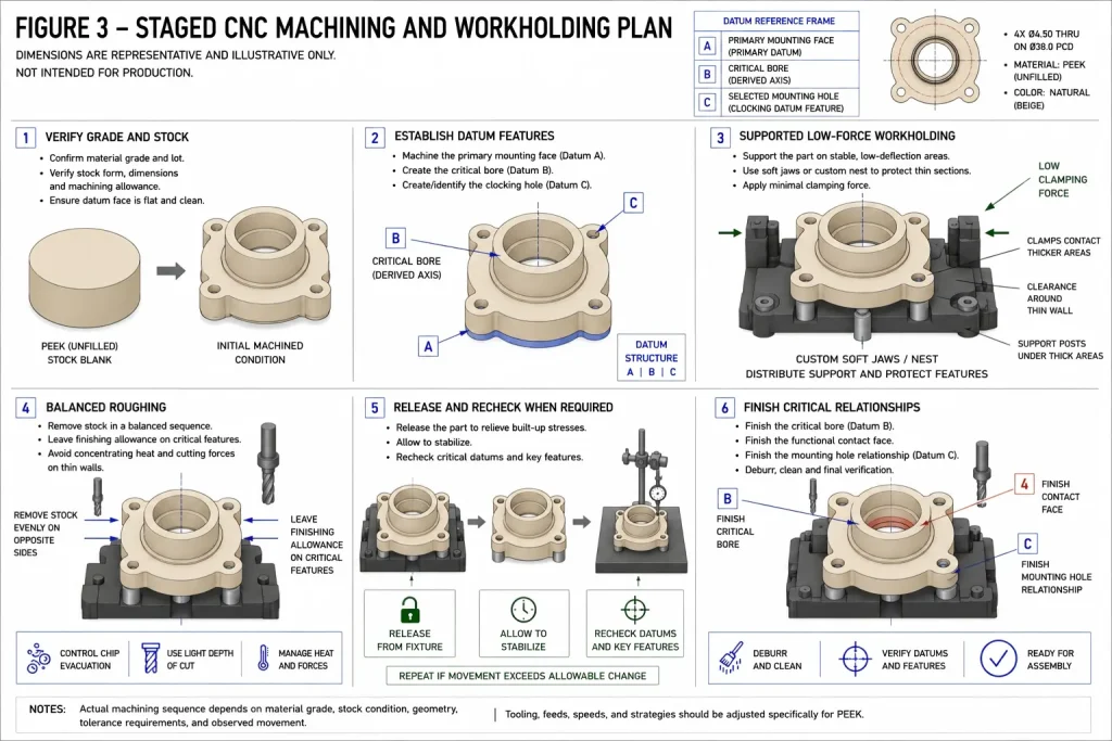
1. Verify Material and Stock Condition
Before programming, confirm:
- Exact PEEK grade
- Filler condition
- Stock form
- Available certificate or lot information
- Stock dimensions
- Visible surface defects
- Required grain, extrusion, or stock orientation where relevant
- Available machining allowance
A substitute PEEK grade should not be introduced without review.
2. Establish Stable Reference Features
The first operation establishes the surfaces needed for reliable relocation.
The process should avoid finishing all critical features immediately. Initial datums may need to be rechecked after substantial material removal.
3. Rough the Main Geometry
Roughing removes the majority of unnecessary material while leaving suitable finishing allowance.
Where geometry permits, material removal should be balanced to reduce one-sided stress release and unnecessary thermal concentration.
The roughing strategy may include:
- Alternating between opposing regions
- Leaving thin walls supported until later
- Avoiding full-depth finishing cuts during the roughing stage
- Maintaining sufficient material around the critical bore
- Removing chips before they are recut
- Monitoring any movement after unclamping
4. Stabilize and Recheck When the Risk Justifies It
A separate stabilization stage is not mandatory for every PEEK part.
It becomes worth considering when:
- Stock removal is substantial
- Walls are thin
- The geometry is asymmetric
- The tolerance chain is sensitive to datum movement
- Trial machining shows measurable free-state movement
- The part changes after release from the fixture
The component may be unclamped, allowed to reach the defined condition, and rechecked before critical finishing.
The required sequence and time should be based on the material, geometry, trial results, and production plan rather than an arbitrary waiting period.
5. Finish the Critical Relationships
The bore, contact face, and mounting-hole relationship should be finished using the most stable practical datum structure.
Where feasible, related features are completed in the same setup or through a controlled datum-transfer plan.
Finishing decisions include:
- Tool condition
- Cutting engagement
- Finishing allowance
- Toolpath direction
- Bore-finishing method
- Hole-making sequence
- Chip evacuation
- Thermal condition
- Tool-offset verification
Five-axis machining may reduce setups for a suitable complex component, but it is not automatically required for PEEK tolerance control. A well-planned three-axis or multi-setup process may be more practical for simpler geometry.
6. Deburr and Clean Without Changing the Functional Edges
PEEK burrs should not be removed through uncontrolled scraping or aggressive polishing near critical features.
The deburring plan should distinguish between:
- Functional edges
- Sealing edges
- Thread starts
- Bore entrances
- Cosmetic edges
- Sharp edges intentionally retained by the drawing
Cleaning materials must also be compatible with the specified PEEK grade and project requirements.
Tooling and Heat Management
Tooling should be selected according to the grade and feature rather than by applying one “PEEK tool” to every project.
For the unfilled material in this representative case, the starting strategy emphasizes:
- Sharp cutting edges
- Controlled radial and axial engagement
- Suitable relief geometry
- Reliable chip evacuation
- Limited rubbing
- Stable tool reach
- Tool-condition monitoring
- Separate roughing and finishing tools where the project justifies it
Fibre-filled grades may increase abrasive wear and can require a different tool-life strategy. PCD or other wear-resistant tooling may be useful in some reinforced-material or repeat-production applications, but it is not a universal requirement for CNC-machined PEEK.
Cooling and chip removal may use air, compatible coolant, or another controlled method depending on:
- Grade
- Feature
- Surface requirement
- Contamination limits
- Cleaning process
- Production quantity
- Machine configuration
The goal is controlled cutting and repeatable measurement—not a dramatic cooling label or a fixed temperature claim.
Inspection Must Match the Drawing
CMM inspection is useful for related geometric features, but it is not the correct tool for every dimension.
| Feature | Possible Inspection Method | Important Condition |
|---|---|---|
| Critical bore size | Bore gauge, suitable internal measuring system, or CMM strategy | Defined measurement depth and stabilized condition |
| Bore position or axis relationship | CMM | Correct datum reference frame |
| Mounting-hole pattern | CMM, optical system, or functional fixture where appropriate | Drawing-based datum alignment |
| Contact-face flatness | CMM, surface plate method, or other suitable system | Free or restrained state must be defined |
| External thickness | Micrometer or suitable dimensional system | Avoid measurement force that deforms the part |
| Threads | Thread gauge and visual inspection | Burr-free entry and defined acceptance |
| Edge condition | Magnified visual inspection where needed | Drawing-defined break edge or sharp-edge requirement |
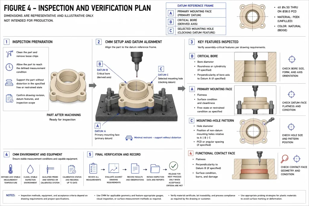
A report should identify:
- Drawing number and revision
- Material and grade where required
- Inspected part quantity
- Inspection condition
- Datum alignment
- Nominal value
- Tolerance
- Actual result
- Pass/fail result where applicable
- Applicable report or equipment traceability
A green result alone does not show whether the correct part, drawing revision, datum structure, condition, and features were inspected.
Our guide to CMM inspection for CNC machined parts explains what buyers should verify in a dimensional report.
What the Process Plan Is Intended to Control
| Project Risk | Process Response | Verification Point |
|---|---|---|
| Clamping-related movement | Low-force, distributed support based on functional datums | Compare restrained and free-state condition where applicable |
| Cutting-heat movement | Sharp tools, controlled engagement, and reliable chip removal | Inspect after the part reaches the defined condition |
| Movement after heavy stock removal | Balanced roughing and staged finishing when justified | Recheck reference features before critical finishing |
| Bore or hole-pattern drift | Protect related datums and reduce unnecessary setup transfer | Verify size and location using the required datum frame |
| Tool-wear drift | Tool-condition and feature-size monitoring | Track actual results across the batch |
| Burrs or damaged edges | Material-specific deburring and cleaning | Inspect critical entrances, sealing edges, and threads |
| Inspection disagreement | Define measurement method and part condition before production | Match the report to the drawing and acceptance plan |
This table describes the purpose of the process plan. It is not a record of guaranteed production results.
Actual capability must be confirmed from the drawing, material, trial machining where required, production controls, and inspection results.
What This Representative Case Demonstrates
Reliable PEEK tolerance control does not come from treating the material like steel, aluminum, nylon, or POM.
It comes from connecting:
- Exact material grade
- Stock condition
- Functional datum structure
- Fixture restraint
- Material-removal balance
- Cutting heat
- Tool condition
- Finishing sequence
- Part stabilization
- Inspection condition
The most important drawing requirement may not be the smallest printed tolerance. It may be the relationship between a bore, contact face, and mounting pattern after the part is released from the fixture.
This representative case also shows why a supplier should not promise a universal PEEK tolerance before reviewing the feature, size, geometry, grade, quantity, workholding, and measurement method.
For custom parts with assembly-critical dimensions and datum relationships, review our precision machining services.
Information to Provide Before Quotation
For a PEEK machining review, provide:
- 3D model
- 2D drawing and revision
- Exact PEEK manufacturer and grade
- Filled or unfilled condition
- Stock-form requirement
- Critical dimensions and GD&T
- Operating-temperature range
- Chemical or cleaning exposure
- Electrical or insulation requirements
- Required edge condition
- Free-state or restrained inspection requirement
- Prototype and production quantities
- Material-certificate requirements
- Dimensional-report or CMM-report requirements
Rapid Efficient can review the drawing, material, geometry, tolerance relationships, inspection priorities, quantity, and delivery requirements before confirming a suitable manufacturing route.