REPRESENTATIVE ENGINEERING CASE
This engineering case uses a simplified aluminum housing model to demonstrate how datum planning, workholding, tool access, machining sequence, and inspection can be connected during a five-axis manufacturing review.
It is not presented as a customer production record. The illustrated geometry, material, datum scheme, process route, and inspection questions must be validated against the actual project drawing before quotation or production.
Representative Housing and Manufacturing Scope
The simplified model is a near-rectangular equipment housing with:
- A deep central cavity
- A broad mounting interface
- A central locating feature
- Two connector ports on different faces
- A mounting-hole pattern
- Relatively thin walls around the cavity
- Internal transition surfaces
- Features that may need to remain related across several machining directions
For process discussion, 6061-T651 aluminum plate is used as an illustrative design basis. The actual alloy, temper, stock form, material condition, and certification requirements must come from the RFQ.
| Project Item | Representative Design Basis |
|---|---|
| Part type | Machined aluminum equipment housing |
| Material for process discussion | 6061-T651 aluminum plate; actual specification must follow the RFQ |
| Production stage | Prototype or low-volume production |
| Main geometry | Deep cavity, multi-side ports, mounting holes, locating feature and thin-wall regions |
| Main manufacturing question | Can related features be accessed without unnecessary datum transfers? |
| Possible five-axis use | Indexed positioning for suitable multi-directional features |
| Main risks | Datum transfer, fixture interference, tool overhang, material movement and inspection access |
| Inspection planning | Define functional alignment and reported characteristics from the drawing |
The model is designed to demonstrate process-planning questions, not to prescribe a universal housing design.
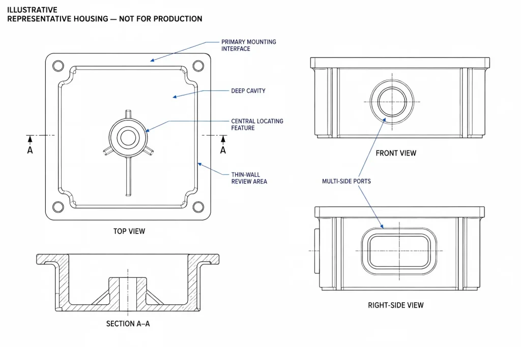
The reason to consider five-axis machining is not simply that the component contains features on several sides. The decision depends on whether controlled reorientation can improve tool access while protecting the functional relationships among the mounting interface, locating feature, ports, and internal geometry.
The Feature Relationships That Drive the Process
A housing may contain dozens of dimensions, but only some of them control assembly.
For the simplified model, the important questions concern the relationship among:
- The mounting interface
- The central locating feature
- The two connector ports
- The mounting-hole pattern
- The cavity and internal interfaces
- The thin walls surrounding those features
A connector port can meet its individual diameter requirement and still create an assembly problem if its axis is incorrectly located or oriented relative to the mating structure.
The drawing review should therefore identify:
- Which surface or feature establishes primary orientation
- Which feature provides secondary location
- Which feature controls clocking when required
- Which ports and holes must remain related
- Which relationships should be machined from a common reference
- Which features can tolerate a setup transfer
- Which relationships require coordinate-based inspection
- Whether the finished part is inspected freely or under defined restraint
For illustration, the simplified drawing may identify the mounting interface as datum feature A, the central locating feature as datum feature B, and a selected clocking feature as datum feature C.
This is an illustrative datum scheme, not a universal rule for aluminum housings. The actual datum reference frame must come from assembly function and the governing drawing.
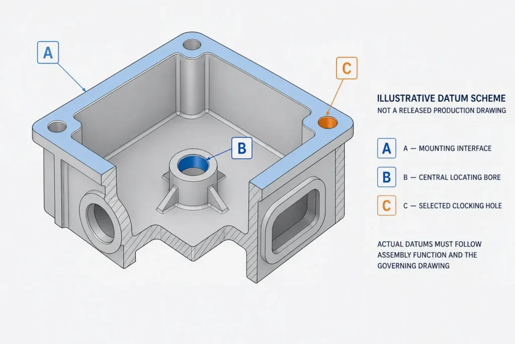
Additional setups are not automatically a problem. Risk increases when assembly-critical features are machined from different references and the transfer variation becomes part of the functional tolerance chain.
The combined effect of datum selection, setup transfer, workholding, and inspection alignment is discussed in our CNC tolerance stack-up guide.
Why Five-Axis Access May Reduce Datum Transfers
A three-axis machining center can produce many complex aluminum housings successfully.
The relevant question is not whether three-axis machining is sufficiently accurate. The question is how many times the component must be manually transferred and re-established to access its related features.
A conventional multi-setup route may require the housing to be:
- Removed from its fixture
- Rotated into another orientation
- Re-clamped
- Located from another physical reference
- Indicated or probed again
- Machined from the new direction
Variation may enter through:
- Fixture contact
- Workpiece seating
- Datum cleanliness
- Clamping pressure
- Indicating or probing strategy
- Material movement
- Thermal condition
- Coordinate transfer
For features with generous relational requirements, this variation may be acceptable.
For ports and mounting features that must remain connected to the same functional reference structure, unnecessary transfers can make the process harder to control.
Five-axis positioning may allow the machine to present several faces to the tool while the component remains in a controlled fixture condition.
That does not mean the complete housing will always be finished in one setup. The original clamping face, underside, or another obstructed feature may still require a controlled second operation.
Indexed positioning for fixed-angle features
The ports in the simplified model represent features that may be machined using indexed 3+2 positioning.
The rotary axes orient the housing and then remain fixed while the cutting operation is performed.
Depending on the drawing and feature geometry, the machining operations may include:
- Spotting
- Drilling
- Circular milling
- Boring
- Counterboring
- Thread milling
- Local face machining
Indexed positioning may reduce manual transfers when the tool, holder, fixture, machine travel, and required feature direction allow the operation to be completed from a fixed orientation.
Do not assume simultaneous five-axis machining
Simultaneous five-axis machining is not assumed for this housing.
It should only be considered for a surface where the CAD geometry and collision review show that the required tool orientation needs to change during cutting.
A curved internal transition does not automatically require simultaneous five-axis motion. Depending on its geometry, it may be machined using:
- Three-axis milling
- Indexed 3+2 positioning
- Form tooling
- A different cutter orientation
- Simultaneous five-axis motion
The simplest suitable strategy should remain preferred.
Datum-Based Workholding and Rotary Clearance
The fixture must do more than hold the housing securely. It must also allow the machine to reach the required features as the workpiece orientation changes.
A representative workholding concept may include:
- Broad support near stable regions
- Controlled locating contacts
- Clearance around thin walls
- Support beneath areas exposed to heavier cutting
- Open access to the connector ports
- Probe access to selected reference features
- Space for spindle and holder movement
- Chip-clearance paths
- Features reserved for a later setup
The fixture should not force the housing into a temporary shape.
If thin walls or a broad mounting surface are distorted by clamping, the part may move after release even when its in-process dimensions appear acceptable.
The design datum is also not automatically the first machining datum.
The initial operation may establish provisional machining references or selected functional features, depending on:
- Stock condition
- Available clamping surfaces
- Machining allowance
- Roughing requirements
- Final datum accessibility
- Fixture design
The final mounting interface should not automatically be completed before heavy cavity roughing unless the process review supports that sequence.
Check the complete rotary envelope
A clamp that is clear when the rotary table is horizontal may interfere with:
- The spindle
- The tool holder
- The cutting tool
- The probe
- The rotary table
- The workpiece itself
after the table or head changes orientation.
Fixture and CAM review should confirm:
- Required rotary-axis travel
- Spindle and holder clearance
- Tool reach
- Collision margin
- Access to both ports
- Access to the cavity
- Probe approach directions
- Chip evacuation
- Safe approach and retract paths
A fixture that blocks the required orientation can remove the practical advantage of five-axis access.
More thin-wall and fixture-related considerations are covered in our guide to reducing deformation during CNC machining.
Representative Machining Route
The following route illustrates the decisions that may be reviewed for this housing. It is not a released production process.
1. Confirm the RFQ baseline
Before programming, confirm:
- Current CAD model
- Drawing revision
- Aluminum alloy and temper
- Required stock form
- Available machining allowance
- Critical dimensions and GD&T
- Surface-finishing requirements
- Inspection condition
- Required reports
- Production quantity
Model and drawing revisions must agree before fixture, CAM, and inspection planning begin.
2. Establish stable machining references
The first operation may create provisional references or selected functional features needed to locate the housing repeatably.
Possible reference features include:
- A stable planar surface
- A locating bore or boss
- A clocking feature
- Controlled fixture-contact areas
The initial references should support the next machining stage without unnecessarily locking the process into an unsuitable final datum interpretation.
3. Rough the central cavity
The cavity represents the largest stock-removal volume.
The roughing strategy may need to consider:
- Tool engagement
- Step-down depth
- Chip evacuation
- Cutting-force direction
- Remaining wall support
- Finishing allowance
- Stock distribution
- Heat accumulation
- Separate roughing and finishing tools
Heavy, unbalanced stock removal may change the part’s geometry as residual material stress is released.
Thin walls and critical interfaces should retain sufficient support and finishing allowance during early roughing.
4. Review movement before critical finishing
Trial results may justify releasing fixture restraint, checking the part in the specified condition, and re-establishing the machining reference before critical finishing.
This is a process decision. It is not a universal rest cycle and should not be described as thermal stress relief.
The need for an intermediate recheck depends on:
- Alloy and temper
- Stock form
- Removed volume
- Wall thickness
- Geometry
- Fixture restraint
- Trial measurements
- Final tolerance relationships
There is no universal waiting time or stock-removal percentage.
5. Index the housing for accessible side features
The housing may then be indexed to present suitable side ports or mounting features to the tool.
Before selecting this route, confirm:
- Tool access
- Holder clearance
- Port diameter and depth
- Entry and exit conditions
- Counterbore or thread requirements
- Chip evacuation
- Burr-sensitive intersections
- Rotary travel
- Datum continuity
The ports are not automatically assigned to 3+2 machining. Indexed machining becomes appropriate only when the geometry and machine configuration support a fixed cutting orientation.
6. Select the simplest suitable route for internal geometry
Internal transitions and cavity surfaces should be reviewed individually.
Possible strategies may include:
- Three-axis milling
- Fixed-angle indexing
- Shorter tooling after reorientation
- Rest machining
- Local simultaneous five-axis motion
Simultaneous motion should not be added merely to make the process appear more advanced.
7. Finish the related functional features
Where practical, strongly related features may be finished from the same verified reference condition.
Depending on the drawing, these may include:
- Mounting interface
- Locating feature
- Connector ports
- Mounting-hole pattern
- Internal assembly interfaces
The final sequence must be based on the functional tolerance chain rather than the visual prominence of each feature.
8. Use a controlled additional setup where required
The original clamping face or another blocked feature may require an additional setup.
This does not invalidate the five-axis strategy.
The later setup should reuse stable locating features where practical and should avoid unnecessarily redefining the relationships already established between assembly-critical features.
Process decision boundary
For the simplified model:
- Multi-directional features demonstrate where indexed access may reduce manual transfers.
- Simultaneous five-axis motion is not assumed.
- Heavy cavity roughing may justify an intermediate reference check.
- Thin-wall dimensions may require inspection after release.
- An additional setup remains acceptable for inaccessible geometry.
- Final machining decisions require the actual CAD model, drawing, fixture, machine envelope, and inspection requirements.
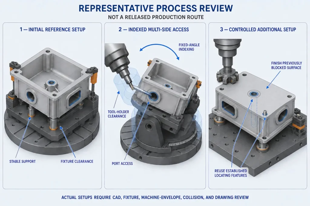
The advantage being evaluated is reduced reference-transfer risk and improved access—not a promise of single-setup machining, fixed accuracy, or shorter lead time.
Inspection Questions Before Production
In-process probing may help verify selected machining references, but it does not prove that the finished housing meets every drawing requirement.
Depending on the equipment and process, probing may support:
- Initial workpiece location
- Selected datum checks
- Shift detection
- Reference confirmation after re-seating
- Measurement of suitable accessible features
Probing does not eliminate:
- Tool wear
- Thermal movement
- Fixture deformation
- Rotary-axis error
- Workpiece distortion
- Incorrect datum interpretation
- CAM programming errors
Final inspection should reproduce the drawing’s datum logic.
A CMM alignment measures the specified datum features and establishes the coordinate system used to evaluate the required feature relationships.
For the simplified model, the inspection review should resolve the following questions:
| Representative Feature | Inspection Question to Resolve |
|---|---|
| Mounting interface | What form or orientation control applies, and is this feature used for alignment? |
| Central locating feature | Does the drawing use its surface, center, or derived axis as a datum feature? |
| Clocking feature | Which feature establishes rotational alignment? |
| Connector ports | Are size, orientation, position, profile, or another characteristic required? |
| Mounting-hole pattern | Which datum reference frame controls the pattern? |
| Internal interfaces | Which dimensional or geometric relationships affect assembly? |
| Thin-wall regions | Is measurement required in a free or restrained state? |
| Finished surfaces | Are dimensions specified before or after anodizing or another finish? |
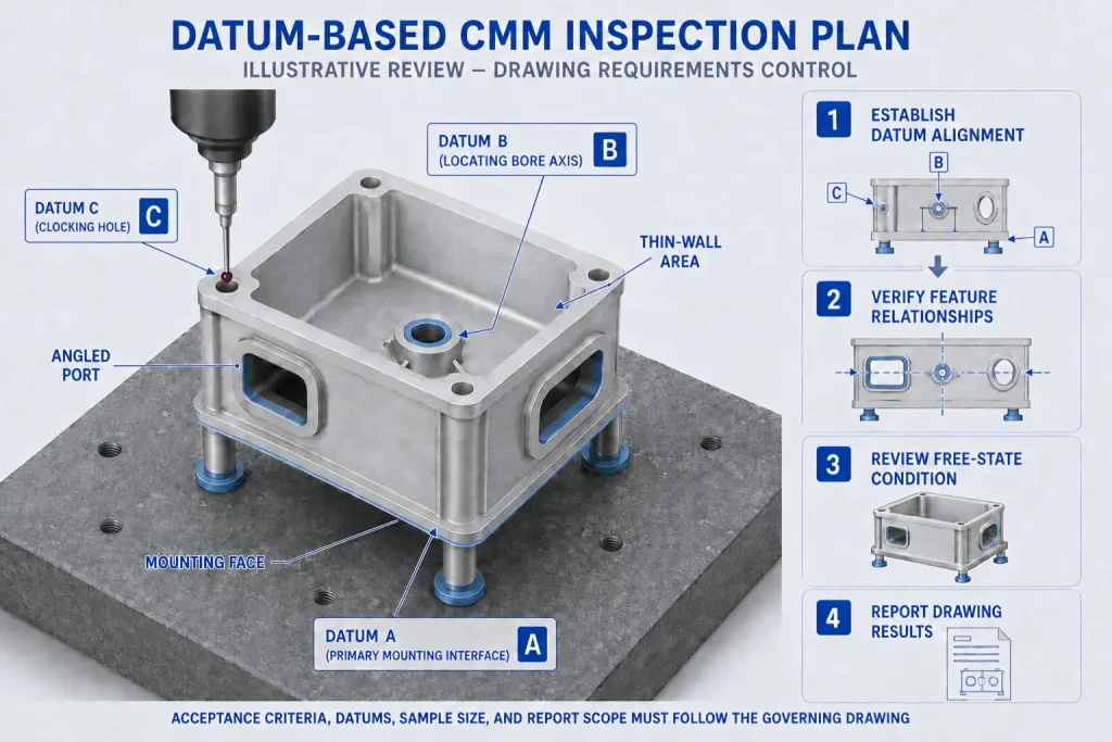
Before quotation, the buyer and supplier should agree on:
- Drawing revision
- Inspected quantity
- Critical characteristics
- Datum alignment
- Measurement condition
- Required report format
- Sampling or full-inspection scope
- Applicable finishing state
A CMM report does not automatically include every dimension on the drawing.
Simple sizes or functional characteristics may be better checked using micrometers, bore gauges, pin gauges, thread gauges, surface-texture instruments, or dedicated functional gauges.
Additional buyer-side checks are covered in our CMM inspection guide for CNC machined parts.
Projects involving multi-directional features, deep cavities, thin walls, or setup-sensitive relationships can also be reviewed through our five-axis CNC machining services.
Information Required Before Quotation
For a five-axis aluminum housing review, provide:
- 3D STEP or equivalent CAD model
- 2D drawing and revision
- Aluminum alloy and temper
- Required stock form
- Critical dimensions and GD&T
- Functional datum structure
- Angled-hole or connector-port requirements
- Thread and counterbore requirements
- Thin-wall regions
- Mating, locating and sealing surfaces
- Surface-finish requirements
- Anodizing, blasting, masking or other finishing requirements
- Prototype and production quantities
- Required inspection characteristics
- Free-state or restrained inspection requirements
- CMM or dimensional-report format
- Inspected quantity
- Material-certificate requirements
- Delivery priorities
Rapid Efficient can review the geometry, material, datum relationships, tool access, workholding constraints, finishing requirements, inspection scope, quantity, and delivery requirements before confirming a suitable machining route.