A CNC-turned brass connector may appear simple, but its functional performance can depend on several closely related features: thread engagement, mating diameters, burr-sensitive edges, plated surfaces, and electrical contact conditions.
This manufacturing case explains how these requirements should be converted into a practical machining and inspection plan.
Customer identifiers and proprietary dimensions are omitted. The focus is the engineering logic required to control the part without publishing unsupported production results or electrical-performance claims.
Project Scope
| Item | Reviewed Requirement |
|---|---|
| Part family | CNC-turned brass electrical connector body |
| Primary geometry | Cylindrical body with threaded, locating, shoulder, and contact features |
| Manufacturing route | CNC turning with secondary drilling or milling when required |
| Critical risks | Thread variation, burrs, coating buildup, incorrect mating dimensions, and undefined inspection state |
| Material | Exact brass grade must be specified or approved before stock is purchased |
| Surface treatment | Plating only when required by the drawing or application |
| Functional verification | Dimensional, thread, edge, finish, and project-specific electrical checks |
| Published boundary | Customer identity, exact dimensions, quantities, and acceptance data are omitted |
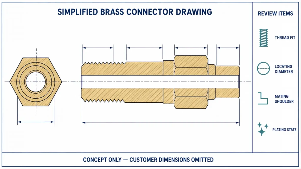
The manufacturing route must protect the features that control assembly. Cosmetic appearance alone cannot confirm thread fit, contact performance, or electrical behavior.
Critical Features and Failure Risks
Thread acceptance
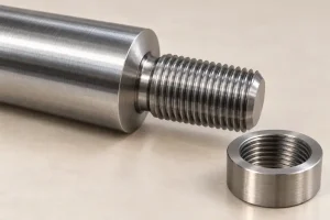
A thread note should define the applicable standard, nominal size, pitch, tolerance class, engagement length, and required inspection method.
Visual appearance is not a reliable acceptance method. A thread may look clean while still creating assembly problems because of:
- Pitch-diameter variation
- Incomplete thread form
- Tool wear
- Burrs at the thread start
- Chips or contamination
- Plating buildup
- An undefined mating component
GO/NO-GO gauges can verify functional limits when the correct calibrated gauge is specified. They do not report every thread characteristic or guarantee behavior with an undefined mating part.
Burr-sensitive edges
Burrs may remain around thread starts, grooves, shoulders, cross holes, cut-off faces, and secondary-machined features.
These burrs can interfere with assembly, damage a mating part, break loose during use, trap contamination before plating, or alter a contact edge.
The drawing should distinguish among:
- Edges requiring a controlled break
- Features with a maximum permitted burr
- Contact edges that must be protected
- Functional edges that must not be excessively rounded
A general note such as “deburr all edges” may not provide enough control for a small connector.
Mating diameters and shoulders
The connector body may use an outside diameter, bore, shoulder, or end face to establish position in the assembly.
These features should be reviewed together rather than as unrelated dimensions. The drawing should identify:
- The functional datum
- The mating component
- Final dimensional limits
- Required fit or clearance
- Concentricity or run-out requirements when functional
- Whether the dimension applies before or after plating
For more detail on fit and post-finishing decisions, review the CNC machining tolerances guide.
Electrical requirements
Material selection and dimensional inspection do not independently prove low contact resistance or stable conductivity.
Electrical behavior may also depend on:
- Exact alloy
- Plating material and thickness
- Contact geometry
- Contact pressure
- Surface cleanliness
- Oxidation
- Mating material
- Assembly torque
- Operating temperature
- Test method
When electrical performance is critical, the RFQ should define the test condition, fixture, measurement method, and acceptance limit.
Manufacturing Decisions
Establish the functional datum chain
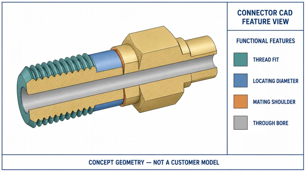
For a rotational connector body, the machining setup should protect the relationship among the thread, bore, locating diameter, shoulder, and end face.
Where practical, concentric features should be machined from a consistent setup or datum strategy.
If the component also contains cross holes, flats, slots, or side features, the secondary operation should reference the functional turned geometry rather than an unrelated cosmetic surface.
Select the machining route from the geometry
A suitable route may include:
- Drawing and material review
- Facing and datum preparation
- Rough and finish turning
- Drilling or boring
- Internal or external threading
- Grooving or cut-off preparation
- Secondary drilling or milling
- Controlled deburring and cleaning
- In-process inspection
- Plating when specified
- Final-state inspection and protected packaging
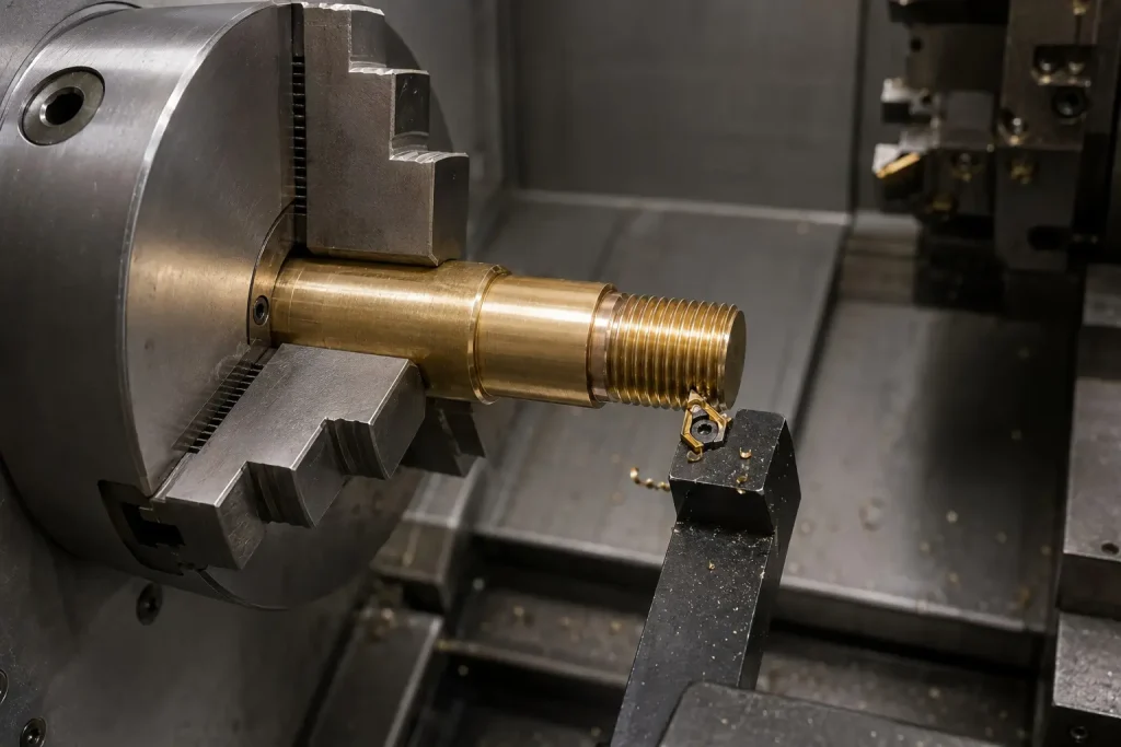
For suitable geometries and quantities, bar-fed production may support consistent material handling and cycle control. It is not automatically required for every connector project.
Rapid Efficient’s CNC turning services support threaded bodies, sleeves, adapters, bushings, shafts, and related rotational components.
Control threading and tool wear
Threading strategy depends on the material grade, thread geometry, tool alignment, cutting conditions, chip evacuation, and required quantity.
The manufacturing plan should review:
- Threading tool geometry
- Thread-start condition
- Run-out or relief geometry
- Chip control
- Tool-wear monitoring
- In-process gauge frequency
- Cleaning before inspection
- Protection during handling
- Reinspection after plating when required
A dedicated threading tool may improve process consistency, but it does not replace gauge control or mating-part review.
Deburr without changing functional geometry
Uncontrolled manual polishing or aggressive tumbling may round thread starts, shoulders, and contact edges.
The deburring method should be selected from:
- Burr location
- Thread size
- Cross-hole access
- Edge function
- Surface-finish requirement
- Plating route
- Permitted edge break
The required result is not simply “no sharp edges.” It is an edge condition that matches the drawing and preserves assembly function.
Plan plating before releasing machining dimensions
Plating may increase an outside diameter, reduce a bore, or change thread engagement. Coating distribution may also vary around recesses and thread roots.
Before production, confirm:
- Plating type
- Required thickness
- Surfaces to be plated
- Masked surfaces
- Contact areas
- Pre-plating dimensions
- Final plated dimensions
- Post-plating thread inspection
- Appearance requirements
- Required coating evidence
A visually uniform coating does not automatically prove thickness, thread fit, adhesion, or electrical performance.
Inspection Plan
Inspection should follow feature function and the condition specified on the drawing.
| Feature | Main Risk | Verification to Review | Inspection State |
|---|---|---|---|
| Internal or external thread | Interference, looseness, damaged thread, burrs, or coating buildup | Correct GO/NO-GO gauge, visual review, and mating-part check when specified | Before plating, after plating, or both |
| Locating diameter or bore | Incorrect assembly fit | Micrometer, bore gauge, optical measurement, or suitable functional gauge | Final required condition |
| Shoulder and overall length | Incorrect axial engagement | Micrometer, caliper, height measurement, or optical method | As defined by the drawing |
| Concentric relationship or run-out | Misalignment between thread, bore, and locating diameter | Indicator, fixture-based method, or CMM when justified | Specified manufacturing state |
| Burr-sensitive edge | Assembly damage, loose debris, or altered contact geometry | Visual inspection, magnification, edge comparison, or controlled functional check | After deburring and after finishing |
| Plated surface | Incorrect coverage, buildup, masked area, or appearance | Visual inspection and coating-thickness verification when required | After plating |
| Electrical function | Excessive or unstable resistance under the defined condition | Project-specific test fixture and acceptance method | Final specified test condition |
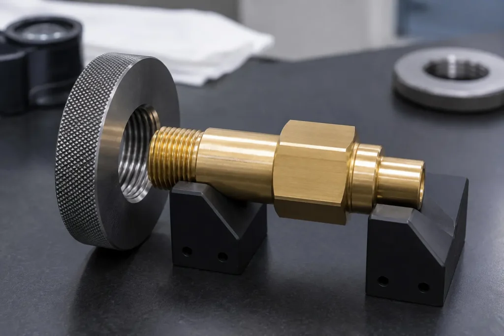
Not every connector requires CMM inspection. Simple rotational features may be inspected more effectively with micrometers, bore gauges, thread gauges, optical equipment, indicators, or functional fixtures.
Inspection equipment should be selected from the feature and acceptance requirement, not added only to make the control plan appear more advanced.
Rapid Efficient’s quality assurance process covers drawing review, material confirmation, in-process checks, final inspection, finishing review, and packaging control.
Review Outcome
The engineering review converts broad requirements such as “clean threads,” “no burrs,” and “stable contact” into defined manufacturing and inspection controls:
- Thread acceptance is linked to the specified standard and gauge.
- Burr-sensitive features are identified on the drawing.
- Functional datums and mating dimensions are separated from cosmetic dimensions.
- Pre-plating and post-plating requirements are clearly distinguished.
- Inspection methods are matched to feature function.
- Mating-part checks are included when required.
- Electrical performance remains tied to a defined functional test.
- Required material, inspection, and coating evidence is agreed before production.
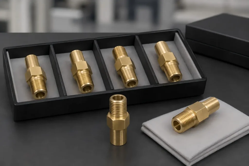
This creates a clearer release package for quotation, machining, inspection, and repeat orders without relying on subjective descriptions or unsupported performance percentages.
Material Selection Note
C36000 free-cutting brass may be suitable when machinability and thread production are priorities.
It should not be selected automatically.
The drawing or RFQ should confirm whether its composition, lead content, conductivity, plating compatibility, mechanical properties, and regulatory status are acceptable for the application.
Another brass grade may be required when the component must meet application-specific restrictions, forming requirements, corrosion conditions, electrical targets, or customer material standards.
Changing the alloy after process development may affect chip formation, burr behavior, thread quality, cycle time, tool wear, and cost.
Send the Functional Requirements With the Drawing
For a brass electrical connector quotation, provide the following information whenever available:
- 2D drawing and 3D model
- Exact brass grade or approved alternatives
- Material certificate and traceability requirements
- Thread standard, size, pitch, class, and engagement length
- Mating-part information
- Critical fits and functional datums
- Burr and edge requirements
- Plating type, thickness, masking, and inspection state
- Electrical test requirements
- Prototype and production quantities
- Inspection-report or sampling requirements
- Packaging and oxidation-protection requirements
Rapid Efficient can review these requirements and coordinate a suitable CNC machining route before quotation.