REPRESENTATIVE CASE STUDY
Achieving Ra 0.8 on Critical Surfaces of a CNC-Machined Aluminum Housing
This case shows how surface-finish requirements were divided by part function and connected to machining, fixturing, inspection, anodizing, and handling decisions.
The drawing and CAD views use simplified, non-customer-identifying project details to explain the engineering process.
Project Overview
The project focused on a CNC-machined aluminum housing with different surface-finish requirements on different functional areas.
| Project Item | Representative Specification |
|---|---|
| Part | Precision CNC-machined aluminum housing |
| Material | Aluminum 6061-T6 |
| Reference Size | Approximately 120 × 80 × 55 mm |
| Main Process | CNC milling with multiple machining and inspection stages |
| Critical Surface Finish | Ra 0.8 μm |
| Controlled Functional Surfaces | Ra 1.6 μm |
| General Machined Surfaces | Ra 3.2 μm unless otherwise specified |
| Surface Treatment | Clear anodizing, nominally 15 ± 5 μm |
| Inspection | Surface-roughness inspection and dimensional verification |
| Main Risks | Built-up edge, chip scratches, chatter marks, inconsistent finishing allowance, and finish damage during handling |
The main goal was not to make every surface equally smooth.
The surface-finish plan had to distinguish between critical mating areas, controlled internal surfaces, and general non-critical faces. This avoided unnecessary finishing work while keeping the important functional areas under tighter control.
Customer and Drawing Requirements
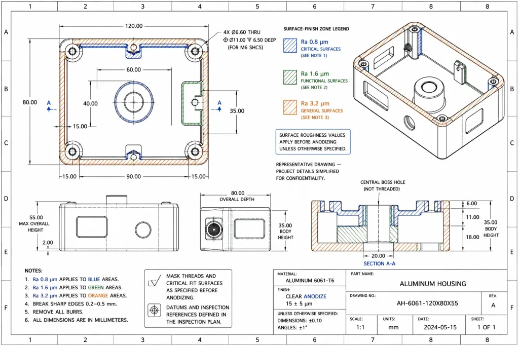
The drawing divided the housing into three surface-finish zones.
Ra 0.8 μm: Critical Surfaces
Ra 0.8 μm was assigned only to selected functional areas where surface condition could affect mating, sealing, positioning, or inspection.
These surfaces required:
- A controlled finishing pass
- Stable tool engagement
- Protection from chip scratches
- Profilometer inspection
- Clear identification on the drawing and inspection plan
Ra 1.6 μm: Controlled Functional Surfaces
Ra 1.6 μm was used for internal or functional surfaces that required a consistent machined finish but did not need the same level of control as the critical faces.
Ra 3.2 μm: General Machined Surfaces
Ra 3.2 μm was used as the general requirement for non-critical machined areas unless another value was specifically shown.
The drawing also included:
- Aluminum 6061-T6 material
- Counterbored mounting holes
- Internal bores and pockets
- Burr and sharp-edge removal
- Clear anodizing
- General dimensional tolerances
A roughness value does not automatically define appearance. Two surfaces with the same Ra can still have different tool marks, scratches, waviness, lay direction, and reflectivity.
Surface-Finish Planning in the 3D Model
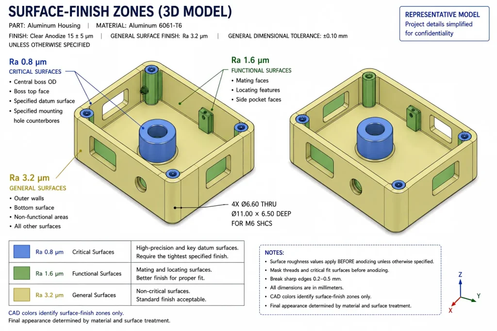
Before machining, the housing surfaces were reviewed by function.
The 3D model was used to separate:
- Critical Ra 0.8 surfaces
- Controlled Ra 1.6 surfaces
- General Ra 3.2 surfaces
- Features requiring protection during later setups
- Areas where chip accumulation could damage an already finished face
This prevented the complete component from being treated as if every surface had the same requirement.
The CAD review also helped identify:
- Tool-access restrictions
- Internal corners
- Long-reach areas
- Large flat surfaces
- Bore and pocket relationships
- Surfaces that could be marked by clamping
- Areas affected by anodizing or masking
CAD display colors are used only to distinguish surface zones. They do not represent the final color of the clear-anodized component.
Why 6061-T6 Was Used for the Housing
6061-T6 is a practical material for machined housings because it provides a useful balance of:
- Strength
- Corrosion resistance
- Material availability
- Machinability
- Anodizing options
- Weight
- Finished-part cost
However, the material alone does not guarantee Ra 0.8.
6061 can still develop:
- Built-up edge
- Smearing
- Burrs
- Long or adhesive chips
- Surface scratches caused by chip recutting
The finishing result depends on tooling, runout, workholding, chip control, machining sequence, and inspection.
For projects requiring a comparison with higher-strength 7075, review our 6061 vs 7075 aluminum guide.
Main Manufacturing Challenges
1. Built-Up Edge on the Cutting Tool
Aluminum can adhere to the cutting edge and change the effective tool geometry.
This may leave:
- Torn areas
- Smearing
- Burrs
- Unstable tool marks
- Local changes in surface roughness
The risk becomes more important during the final pass because a small amount of adhered material can damage an otherwise acceptable surface.
2. Chip Recutting Inside the Housing
The internal pocket and walls can retain loose aluminum chips.
If these chips remain in the cutting zone, they may:
- Scratch a finished surface
- Become trapped beneath the tool
- Damage internal walls
- Create random marks that are not visible in the programmed toolpath
Chip removal therefore had to be planned before each critical finishing pass.
3. Chatter on Walls and Large Flat Surfaces
Long tool reach, unstable engagement, weak support, and excessive overhang can leave periodic vibration marks.
The risk is not limited to appearance. Chatter may also affect:
- Flatness
- Bore geometry
- Edge quality
- Tool life
- Dimensional consistency
4. Inconsistent Finishing Allowance
A finishing tool cannot cut consistently if some areas retain too much stock while other areas have almost no material left.
An inconsistent allowance can cause the tool to alternate between cutting and rubbing.
5. Protecting Finished Surfaces
A surface may meet the machining requirement and still be damaged during:
- Deburring
- Cleaning
- Part transfer
- Anodizing
- Inspection
- Packaging
The process therefore had to include both machining control and post-machining surface protection.
For additional information about built-up edge, chipping, flank wear, and tool replacement, review our CNC tool-wear guide.
Why a Standard One-Pass Strategy Was Not Enough
A simple machining approach might use the same tool, finishing allowance, and cutting condition across every surface.
That approach can create several risks:
- A roughing tool may already have edge wear before the critical finishing pass.
- One feed and speed combination may not suit the top face, pocket floor, walls, and bores.
- Chips may remain inside the housing and scratch completed areas.
- Critical surfaces may be finished too early and damaged during a later setup.
- Surface-roughness inspection may occur only after all parts are complete.
- Unnecessary fine finishing may be applied to non-critical areas.
The project therefore required a surface-specific process rather than one uniform finish strategy.
Optimized Machining and Fixturing Strategy
1. Separate Roughing and Finishing
Roughing removed most of the material while leaving a controlled allowance on the specified finish zones.
Critical surfaces were finished only after:
- Major stock removal was complete
- The part had reached a more stable condition
- The fixture and datum surfaces were cleaned
- The finishing tool had been checked
2. Use a Dedicated Finishing Tool
The final Ra-controlled surfaces were not automatically finished with the same worn cutting edge used for heavy roughing.
The finishing tool was selected to provide:
- A sharp edge
- Suitable aluminum-cutting geometry
- Low runout
- Practical reach
- Stable chip evacuation
3. Control Tool Overhang and Runout
Tool overhang was kept as short as the geometry allowed.
Before critical finishing, the process required checking:
- Toolholder cleanliness
- Spindle-taper contact
- Tool runout
- Cutting-edge condition
- Tool length and reach
- Fixture stability
4. Support the Housing Without Marking Critical Surfaces
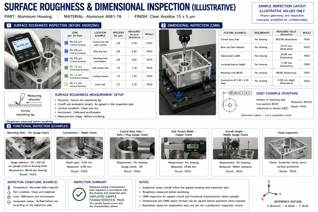
The fixture needed to locate the part from functional datums while distributing clamping force.
The support plan had to avoid:
- Local wall deformation
- Jaw marks
- Part movement
- Blocking tool access
- Contact with completed Ra-controlled surfaces
5. Plan the Finishing Sequence
The sequence prioritized surfaces according to function and damage risk.
A practical order included:
- Rough machining
- Datum and reference-feature preparation
- Semi-finishing
- Critical Ra 0.8 finishing
- Remaining controlled surfaces
- Deburring and controlled cleaning
- Roughness and dimensional inspection
6. Remove Chips Before Critical Passes
The cavity, bore, pockets, and fixture contact surfaces were cleaned before the critical finishing operations.
An appropriate air, coolant, or lubrication strategy was used to reduce chip recutting without creating unstable thermal conditions.
Surface-Roughness Inspection
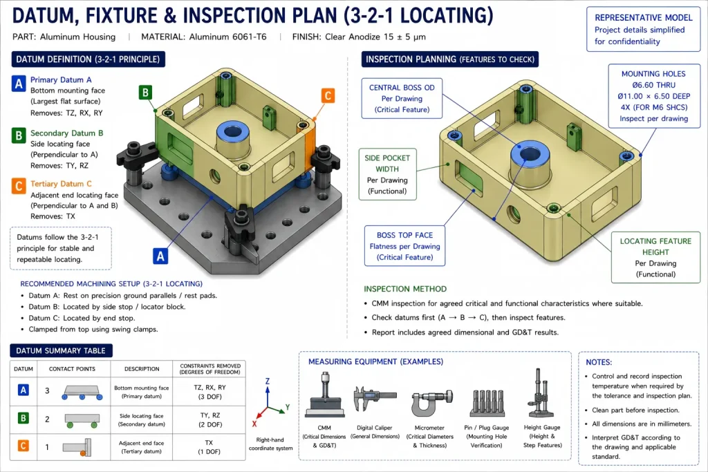
Surface roughness was treated as a separate inspection characteristic rather than judged only from visual appearance.
Before measurement:
- The surface was cleaned.
- The inspection location was matched to the drawing.
- The stylus direction was selected relative to the machining lay.
- The required Ra value was confirmed.
- The instrument settings and evaluation length were recorded when required.
The Ra 0.8, Ra 1.6, and Ra 3.2 zones were evaluated separately.
A surface could not be accepted only because it appeared bright or reflective. Tool marks, scratches, waviness, and local defects also required visual review.
Ra records an average profile value. For sealing or contact surfaces, the drawing may also need to control Rz, waviness, lay direction, or isolated surface defects.
Dimensional inspection remained separate from roughness inspection. A surface can meet its Ra requirement while the related bore, plane, or feature still fails dimensional or geometric tolerance.
Clear Anodizing and Surface Protection
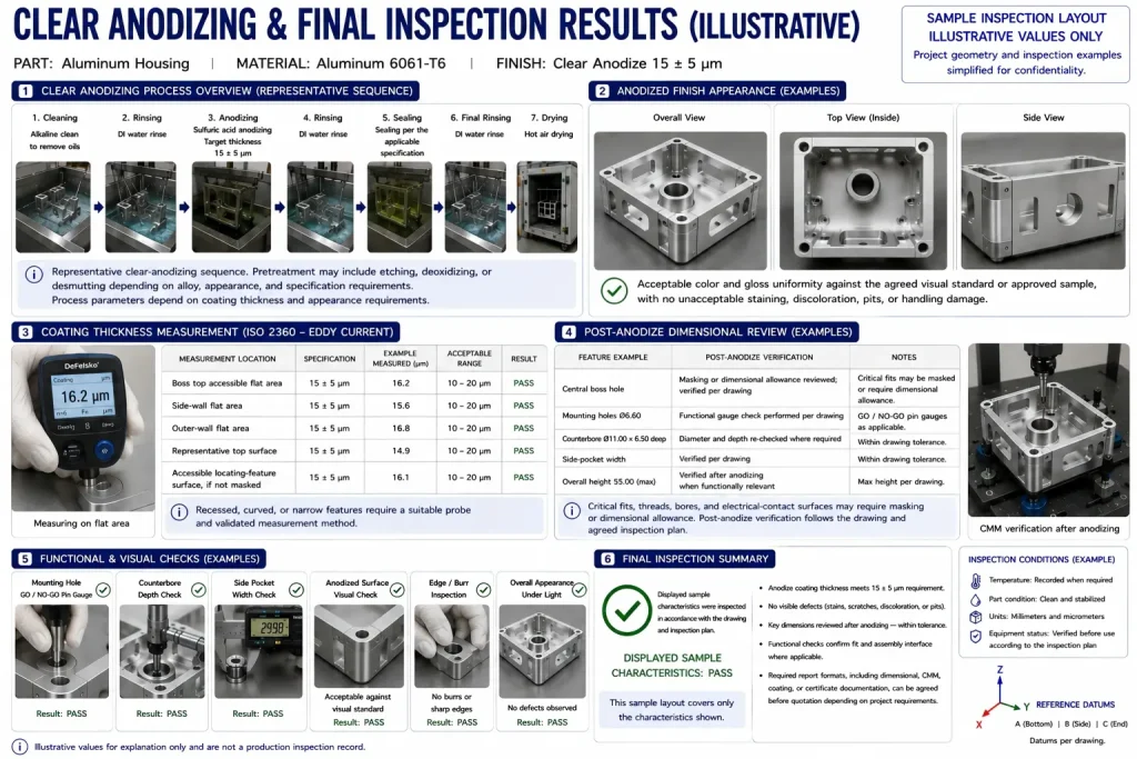
The representative drawing specifies clear anodizing after machining.
The anodizing requirement had to be reviewed together with:
- Surface roughness
- Bore and thread dimensions
- Critical fits
- Masking
- Electrical-contact areas
- Sealing surfaces
- Cosmetic expectations
- Final inspection condition
Clear anodizing does not automatically hide machining marks.
Chatter, scratches, dents, and inconsistent tool paths may remain visible after treatment. The machined surface therefore had to be acceptable before anodizing.
The drawing should also define whether the Ra requirement applies:
- Before anodizing
- After anodizing
- Or at both stages
Threads, bores, and close-fit surfaces may require masking or machining allowance depending on the functional requirement.
What This Project Demonstrates
The main lesson was not that every aluminum surface should be machined to Ra 0.8.
The project showed that better results come from connecting each drawing requirement to a specific process step.
The control plan separated:
- Critical and non-critical surfaces
- Roughing and finishing tools
- Machining and inspection requirements
- Functional dimensions and cosmetic appearance
- Machining quality and post-machining protection
This approach helps avoid two opposite problems:
Overprocessing a general surface that does not require a premium finish
Under-controlling a critical mating or sealing surface
FAQ About This Aluminum Surface-Finish Case
Can 6061 Aluminum Be Machined to Ra 0.8 μm?
Yes, suitable 6061 features can achieve Ra 0.8 μm under a stable process.
The result depends on tool condition, runout, fixture stability, finishing allowance, chip evacuation, feature access, and measurement method.
Does Ra 0.8 Mean a Mirror Finish?
No.
Ra describes average profile roughness. It does not directly define reflectivity, waviness, lay direction, scratches, or cosmetic appearance.
Should Every Surface Be Specified as Ra 0.8?
No.
Only surfaces with a functional or justified cosmetic requirement should receive a tighter roughness specification. General non-critical surfaces may use a less demanding finish.
Is Surface Roughness Measured Before or After Anodizing?
The drawing or inspection plan should define the required condition.
Anodizing can affect surface texture and dimensions, so the requirement should not be left open to interpretation.
Can Surface Finish Be Confirmed by Looking at the Part?
Visual inspection can identify tool marks, scratches, dents, and appearance differences, but it cannot confirm a specified Ra value.
A suitable surface-roughness instrument is required.
Review Your Aluminum Housing Before Production
Send the STEP file, 2D drawing, aluminum alloy and temper, required Ra or Rz values, surface-treatment requirement, critical dimensions, quantity, and inspection requirements.
Rapid Efficient can review:
- Surface-finish zones
- Tool access
- Finishing allowance
- Fixturing and support
- Chip-control risks
- Anodizing and masking
- Roughness inspection
- Dimensional inspection
- Handling and packaging
For custom aluminum housings, brackets, plates, fixtures, and precision components, review our CNC aluminum machining services.