快速解答
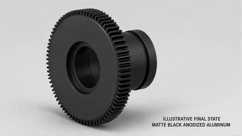
Camera focusing gear machining cannot be controlled by one general “high precision” tolerance. The critical requirement is the relationship between the locating bore, 齿轮齿, reference face, thin-wall condition, and final surface treatment. In this historical project, RapidEfficient coordinated datum preparation, 低变形工件夹具, gear-profile machining, controlled deburring, anodizing allowances, and feature-based inspection around the customer drawing.
项目概况
| 项目项目 | 要求 |
|---|---|
| 成分 | CNC-machined aluminum focusing gear |
| 应用 | Motor-driven camera focusing mechanism |
| 材料 | 铝合金 |
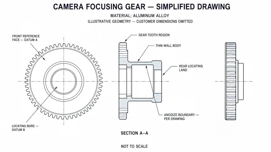
| 主要几何形状 | Thin-wall gear body with a central locating bore and precision tooth region |
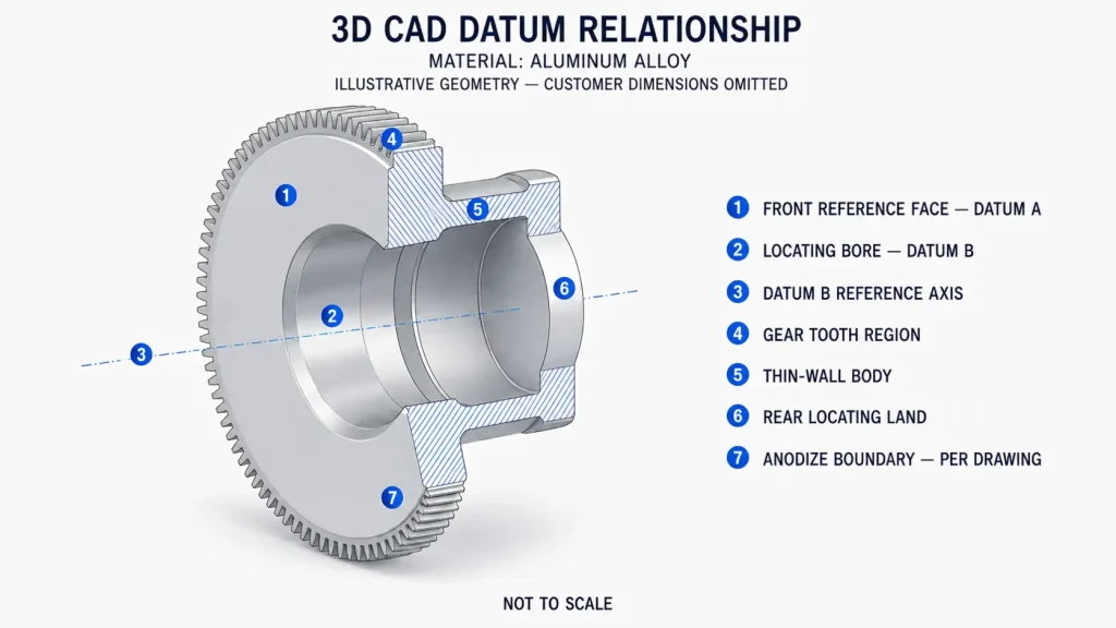
| Functional relationship | 齿轮齿数, locating bore and reference face |
| 表面处理 | Black anodized finish |
| 主要制造风险 | Bore-to-gear misalignment, 钳位畸变, tooth-edge burrs and finishing interference |
| Acceptance basis | Customer drawing and agreed inspection requirements |
保护客户机密, 未公开识别信息和选定的图纸尺寸.

The Main Risk Was Not One “Precision” Number
A focusing gear transfers controlled motor movement into lens movement. Its performance therefore depends on several different characteristics working together.
A bore can meet its size tolerance while the gear teeth still run eccentrically relative to the bore axis. The tooth profile can also be acceptable while the reference face introduces axial movement during rotation.
These characteristics are not interchangeable:
- Bore size controls fit.
- Bore form affects support and rotational stability.
- Gear-to-bore relationship affects radial motion during meshing.
- Reference-face relationship affects axial movement.
- Tooth profile and pitch affect contact and transmission behavior.
- Thin-wall distortion affects the released shape of the complete part.
- Surface treatment can change fits, edges and tooth clearances.
If gear-to-bore eccentricity changes the operating center distance during rotation, meshing resistance and backlash may also vary periodically. The system-level effect still depends on the mating gear, 中心距, 预载, motor torque and control strategy.
The drawing review therefore separated bore size, 孔形式, gear-to-bore relationship, face relationship, and tooth geometry instead of hiding them inside one general “high precision” note.

For a broader explanation of feature-specific tolerances and datum relationships, 看看我们的 CNC加工公差指南.
DFM Review Started With the Transmission Interface
A STEP model can show the nominal gear geometry, but it does not fully define how the gear must function or be inspected.
机加工前, the drawing and assembly information needed to clarify the relationship between the gear and the rest of the focusing mechanism.
| 特征 | Information Needed | Why It Affects Manufacturing |
|---|---|---|
| 齿轮齿数 | 齿数, module or diametral pitch, pressure angle and tooth-form requirements | Defines the cutting tool, machining method and inspection route |
| Locating bore | 公称直径, 合身, depth and final-condition requirement | Establishes the rotational reference and assembly fit |
| Reference face | Datum function and allowable face relationship | Controls axial location and potential face runout |
| Mating gear | 间隙, center distance and mating-part information | Helps define the functional tooth relationship |
| Thin-wall area | Free-state requirement and acceptable support locations | Affects fixture design and released-state inspection |
| 阳极氧化表面 | Coating type, masking areas and post-finish dimensions | Prevents interference at fits, threads and tooth surfaces |
| 检验证据 | Required gear data, dimensional report or functional check | Determines the acceptance method before production |
A gear accuracy grade should also identify the governing standard and the characteristics that must be reported. A quality number without its applicable system, edition and measurement scope is incomplete.
The Machining Route Protected the Bore-to-Gear Relationship
Establish Stable Blank References
对于这个项目, we separated main stock removal from final datum preparation, gear cutting, 去毛刺, 阳极氧化, 和最终检验.
Main stock removal was completed before the final relationship between the locating bore, reference face and tooth region was established. Appropriate stock was retained for later finishing.
Where stabilization between operations was required, the part was released before the next setup so that a temporary clamping shape was not mistaken for the free-state condition.
Finish the Locating Bore and Reference Face
The locating bore and reference face formed the mechanical reference for the rotating component.
These features needed to be prepared and verified before the gear-to-bore relationship could be protected. Locating the later gear-cutting operation from an unrelated outside surface would have created a separate tolerance chain.
Bore size alone was not enough. The process also had to consider bore form, 表面状况, depth and the relationship between the bore axis and the reference face.
Reference Gear Cutting to the Functional Datums
The tooth-generation method depends on the tooth form, 尺寸, 使用权, 材料, quantity and available equipment.

The important project decision was not the machine label; it was how the gear-cutting setup referenced the functional locating features.
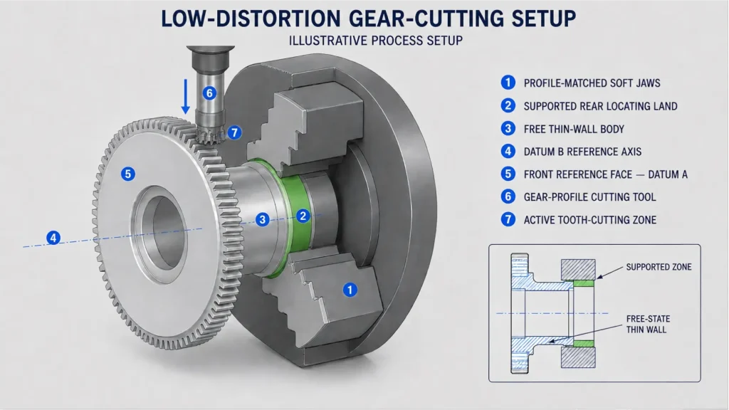
We re-established the gear-cutting setup from the locating bore and reference face so the tooth region remained tied to the functional assembly references rather than an unrelated outside surface.
This does not mean that all operations must always be completed in one setup. A carefully controlled datum transfer can be more appropriate than forcing every feature into one operation.
Low-Distortion Workholding Protected the Thin Gear Body
A thin cylindrical gear body can appear round while held and then recover into a lobed or tapered shape after release.
Local radial pressure is especially risky when the fixture contacts a flexible wall instead of a rigid locating region.
Profile-matched soft jaws were used to distribute the holding load and reduce concentrated contact. Clamping pressure was limited to what was required to resist the cutting force.
The workholding plan also considered:
- Which surfaces could accept fixture contact
- Whether the cutting force pushed the part into or away from its supports
- Access for the gear-cutting tool
- Clearance around the tooth exit side
- Whether the part could be released and rechecked before final acceptance
- Whether the same reference could be reproduced during inspection
After the final machining operation, we released the part before dimensional verification so that fixture restraint did not hide thin-wall springback.
For more detail on springback, local clamping pressure and released-state inspection, 回顾我们的 薄壁铝CNC加工指南.
Tooth-Edge Burrs Required Controlled Removal
Fine gear teeth create small edges at the tooth tips, roots and tool-exit side.
These burrs cannot be treated like heavy burrs on a general structural component. Aggressive hand filing, tumbling or uncontrolled polishing may round the tooth edge, change the effective tooth thickness or damage the flank near the active contact area.
The process therefore combined:
- Sharp cutting edges appropriate for aluminum
- Controlled tool engagement at the tooth exit
- 工具状态监控
- Limited manual intervention
- Magnified visual review where appropriate
- Cleaning after deburring
- Protection from loose particles during handling
The objective was to remove harmful edge material without changing the functional gear geometry.
Any micro-deburring method must be qualified on representative tooth geometry. Abrasive brushing may round tooth edges if it is not controlled, while ultrasonic cleaning can remove loose contamination but should not be treated as proof that attached tooth-root burrs have been removed.
“Burr-free” should not be used as an unlimited promise. The drawing or inspection agreement should define which edges are critical, what magnification is required and whether edge-break limits apply.
Anodizing Was Part of the Tolerance Chain
The project included a black-anodized surface requirement.
Anodizing changes the surface condition and may affect precision bores, 线程, mating faces and gear-tooth clearances. The dimensional effect is not one universal value that can be applied to every aluminum part.
It depends on factors including:
- 铝合金
- Anodizing process
- Required coating condition
- Bath and process control
- 零件几何形状
- 掩蔽计划
- Whether the drawing dimension applies before or after finishing
The DFM review therefore needed to identify whether the locating bore, 齿轮齿, reference face or other fitted features required masking, machining allowance or post-finish verification.
If the gear teeth are anodized, the drawing should define the pre-finish measurement method, coating allowance and required post-finish backlash condition. 通过销或球进行测量, common-normal span or another agreed gear-control method may be used where appropriate, but the compensation cannot be calculated from one universal coating-growth rule.
Black appearance also does not automatically define optical reflectance. If stray-light control is functional, the drawing should specify the required surface preparation, finish boundary and optical requirement instead of relying only on the word “black.”
For a broader comparison of coating behavior and drawing requirements, 看看我们的 铝阳极氧化和粉末涂层指南.
Inspection Had to Match Each Characteristic

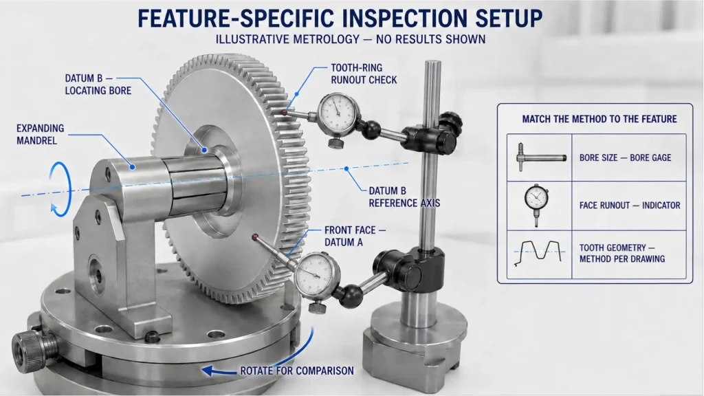
Inspection therefore followed the characteristic being controlled instead of treating a CMM as a universal answer.
| 特征 | Inspection Method to Review | 重要边界 |
|---|---|---|
| Locating-bore size | 内径规, air gauge or suitable plug gauge | Method depends on diameter, 深度, tolerance and quantity |
| 缸径形式 | 圆度设备, scanning method or agreed multi-section evaluation | A single diameter reading does not prove full roundness or cylindricity |
| Gear-to-bore relationship | Gear runout setup using the functional locating bore or an agreed gear-measurement method | Measuring from an unrelated outside diameter may hide datum error |
| Tooth profile and pitch | Gear-measuring equipment or another agreed tooth-evaluation method | Only the characteristics required by the drawing should be reported |
| Functional composite behavior | Agreed master-gear or composite inspection where appropriate | The mating condition and governing standard must be defined |
| Reference-face relationship | Indicator setup or CMM evaluation relative to the locating axis | Face flatness alone does not define rotational face runout |
| Tooth-edge burrs | Magnified visual inspection and defined edge criteria | Inspection must not confuse an allowed edge break with damaged tooth geometry |
| Post-anodize condition | Recheck of selected fits, 线程, tooth clearances and appearance | The drawing must state which requirements apply after finishing |
A CMM can be useful for datum-related position and orientation, but it is not automatically the best instrument for bore size or detailed gear-flank inspection.
同样地, an ordinary caliper cannot verify the functional relationship between a locating bore and a precision tooth region.
An optical comparator may help inspect a visible edge, outline or burr condition when the feature can be presented correctly. It should not automatically be treated as complete verification of pitch, 螺旋, tooth-flank form or composite gear behavior.
Where formal first-piece evidence is required, the drawing and inspection agreement should identify the characteristics, instrument, sampling plan and acceptance condition before production. 我们的 首件检验指南 explains the information buyers should define.
项目成果

The completed focusing gears were supplied for customer assembly after inspection against the project drawing and agreed acceptance requirements.
The case demonstrated that camera focusing gear machining is not solved by selecting a machine advertised as “high precision.”
The more important decisions were:
- Defining the locating bore and reference face
- Protecting the tooth-to-bore relationship
- Supporting the thin wall without locking in distortion
- Controlling tooth-edge burrs without changing the flank
- Treating anodizing as part of the tolerance chain
- Matching each requirement to an appropriate inspection method
Final camera performance still depends on the complete mechanism, including the motor, mating gear, 中心距, 反弹, lens load, control strategy and assembly condition. A machined gear cannot independently guarantee focusing speed, image stability or optical accuracy.
What Buyers Should Include in a Focusing Gear RFQ
进行有用的制造审查, 提供:
- 3D CAD model and controlled 2D drawing
- 铝牌号, 脾气, quantity and required finish
- 齿轮类型, tooth count, module or diametral pitch, pressure angle and helix angle
- Tooth modification and applicable gear-accuracy standard
- Locating-bore fit, datum structure and gear-to-bore relationship
- Mating gear, center distance and backlash requirement
- Thin-wall and released-state inspection requirements
- 阳极氧化, masking and post-finish dimensional requirements
- 伯尔, cleanliness and inspection-report requirements
Review Your Camera Focusing Gear Project
RapidEfficient 提供 精密加工支持 for custom gears, 旋转部件, thin-wall parts and datum-sensitive mechanical components.
To review a camera focusing gear, send the drawing package and gear requirements together with the mating-part information, 材料, 数量, coating boundary, backlash requirement and inspection evidence you need.
We can then review the datum strategy, 工件夹持风险, gear-cutting route, deburring boundary, surface-treatment allowance and inspection plan before quotation.