如何防止 CNC 加工铝零件出现划痕

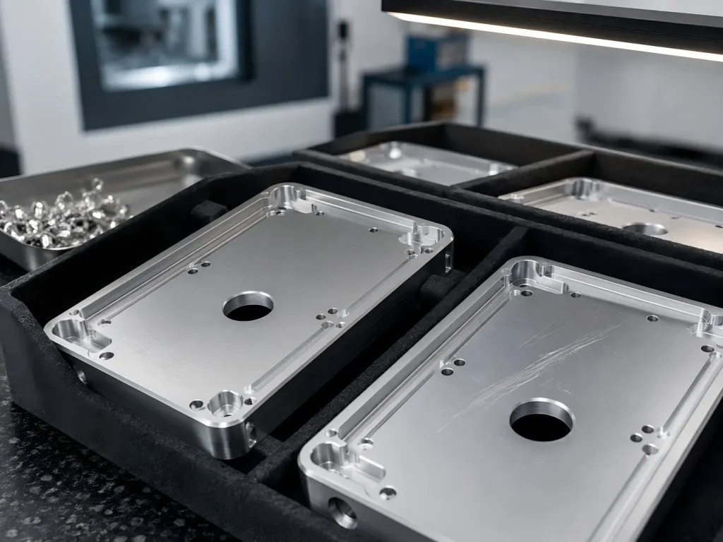
Clean and scratched CNC-machined aluminum housings separated in protective trays under raking light for cosmetic surface inspection.

CNC 加工的铝制零件上的划痕不仅仅发生在切割过程中.

A part may leave the machine with a clean surface and still be damaged during deburring, 打扫, 检查, transfer to anodizing, 集会, 包装, or transportation.

这对于:

  • 装饰外壳
  • 控制面板
  • Camera and optical components
  • Consumer-electronics parts
  • Medical-device enclosures
  • 机器人罩
  • Aluminum frames
  • Anodized brackets
  • Visible assembly components

The practical goal is not to promise that every aluminum surface will be completely free from every microscopic mark. The goal is to identify the surfaces that matter, reduce avoidable damage throughout production, and inspect the finished parts against an agreed appearance standard.


快速解答

To reduce scratches on CNC-machined aluminum parts:

  • Mark cosmetic surfaces clearly on the drawing.
  • Use sharp aluminum-cutting tools and control built-up edge.
  • Remove chips before they are dragged across finished surfaces.
  • Keep jaws, 固定装置, 桌子, trays, and gloves clean.
  • Place clamps and locating points on approved non-cosmetic areas.
  • Plan finishing toolpaths to avoid dwell, tool re-entry, and retract marks.
  • Deburr edges without rubbing abrasive tools across visible faces.
  • Separate parts during cleaning, 检查, 贮存, and transport.
  • Protect parts before anodizing and define acceptable rack locations.
  • Inspect appearance under agreed lighting, distance, angle, and viewing time.
  • Package each cosmetic part so metal surfaces cannot contact each other.

Surface roughness values such as Ra may support process control, but they do not replace visual inspection for isolated scratches, 凹痕, 污渍, or handling marks.


Where Do Scratches on Aluminum Parts Come From?

A visible scratch can be created at almost any stage of production.

Production stageCommon source of scratchingPractical prevention
CNC roughingChips trapped between the tool, 夹具, or partImprove chip evacuation and clean the setup
CNC finishing内置边缘, dull tool, tool re-entry, or chip recuttingUse a stable finishing tool and controlled toolpath
工件夹持Dirty jaws, hard contact points, excessive local pressureUse clean, qualified contact surfaces and suitable soft jaws
Part removalSliding the part across the fixture or machine tableLift the part clear instead of dragging it
去毛刺Abrasive pads or files touching cosmetic facesLimit deburring to specified edges
打扫Chips embedded in cloths, brushes, trays, or glovesUse clean tools, clean trays, and approved cleaning methods
检查Dirty granite, 仪表, 固定装置, or repeated slidingClean all contact surfaces and use protected supports
Anodizing transportParts touching each other in baskets or racksSeparate components and define rack locations
内部交通Mixed parts moving inside a trayUse dedicated pockets or soft separators
包装Metal-to-metal contact or loose partsPackage parts individually or in separated cells
船运振动, compression, or damaged separatorsValidate packaging for the part weight and route
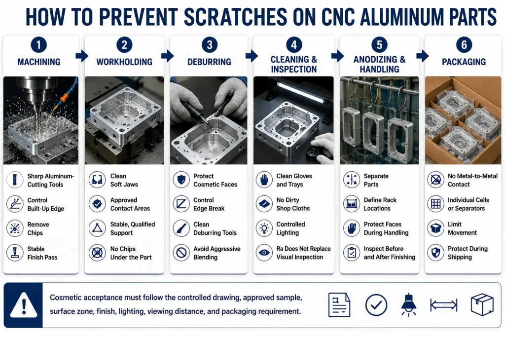
CNC aluminum scratch-prevention workflow covering machining, 工件夹持, 去毛刺, 打扫, visual inspection, anodizing handling, and separated packaging.

For broader issues such as built-up edge, 毛刺, 喋喋不休, 形变, 和芯片疏散, 回顾我们的 aluminum machining problems guide.


1. Define Cosmetic Surfaces Before Machining

Scratch prevention begins with the drawing, not with final inspection.

The supplier needs to know which surfaces are visually critical and which surfaces will be hidden after assembly.

A useful drawing or cosmetic specification should identify:

  • Customer-facing surfaces
  • Surfaces visible after assembly
  • Hidden internal surfaces
  • Clamp-permitted areas
  • Rack-mark-permitted areas
  • Areas covered by labels, 密封, or fasteners
  • Areas requiring protective film
  • Surfaces that must remain electrically conductive
  • Surfaces that will be anodized, 绘, 镀, or bead blasted

Do not rely only on a note such as:

No scratches allowed.

That statement does not define how the part will be evaluated.

Define the Inspection Conditions

The appearance requirement may need to specify:

  • Lighting type and approximate intensity
  • Viewing distance
  • Viewing angle
  • Maximum inspection time
  • Whether the part is viewed before or after finishing
  • Whether the part is dry, 清洁过的, or assembled
  • The approved reference sample
  • Acceptance limits for scratches, 凹痕, 污渍, 工具痕迹, and color variation

Terms such as Class A, Class B, or Class C should only be used when the project has a controlled definition for those classes. Different customers may use different meanings.


2. Control Chips Before They Recut the Surface

Aluminum chips can be sharp enough to mark a finished surface.

During pocketing, 钻孔, or high-material-removal operations, chips may remain inside the cavity and be dragged under the tool or across the workpiece.

Common risk areas include:

  • 财力雄厚
  • 水平壁架
  • 盲孔
  • 细排骨
  • Large flat cosmetic faces
  • 排水不良的固定装置
  • Parts positioned where chips collect around the jaws

Practical Chip-Control Measures

Depending on the machine, 过程, 零件几何形状, and workplace procedure, chip control may include:

  • Suitable flute geometry for aluminum
  • Adequate flute space
  • Through-tool or external coolant
  • Controlled air blast where permitted
  • Toolpaths that move chips out of pockets
  • Periodic chip clearing between operations
  • Cleaning the fixture before the finishing setup
  • Avoiding unnecessary travel across finished faces
  • Separating roughing and finishing tools

The process should prevent chips from being trapped between:

  • The workpiece and soft jaws
  • The workpiece and support points
  • The workpiece and machine table
  • Two stacked parts
  • The part and an inspection fixture

Manual chip removal should only be performed after the machine is in a safe stopped condition and according to the approved workplace procedure.


3. Use Tools Suitable for Aluminum Finishing

A tool that is acceptable for roughing may no longer be suitable for a cosmetic finishing pass.

Aluminum can adhere to the cutting edge. This built-up material changes the effective tool geometry and may produce:

  • Drag marks
  • Torn material
  • Uneven surface texture
  • 毛刺
  • Local gouges
  • Sudden changes in surface finish

Tool Features to Review

The machining plan may consider:

  • 锋利的切削刃
  • Polished flutes
  • Suitable rake geometry
  • Sufficient flute space
  • 受控刀具跳动
  • Short, rigid tool projection
  • Stable toolholding
  • Coatings selected for the alloy and operation
  • Dedicated finishing tools
  • Defined tool-life limits

DLC, 氮化锆, uncoated polished carbide, and other tool options can all be useful in the correct application. No single coating or flute count is best for every aluminum alloy, 机器, coolant system, and feature.

Separate Roughing and Finishing Tools

A finishing tool should not be assumed to remain suitable after long roughing cycles or interrupted cuts.

For high-visibility surfaces, a controlled finishing tool can reduce the risk of:

  • 边缘崩边
  • 内置边缘
  • 尺寸漂移
  • Random texture changes
  • Tool marks that become more visible after anodizing

4. Plan the Toolpath Around Cosmetic Surfaces

Even a sharp tool can leave visible marks when the finishing toolpath is poorly planned.

Potential causes include:

  • Tool dwell
  • Repeated passes over the same area
  • Lead-in or lead-out marks
  • Tool re-entry on a visible face
  • Sudden feed changes
  • Retracting while the cutting edge still touches the wall
  • Finishing across trapped chips
  • Changes in tool pressure at thin sections

Better Finishing Strategy

The exact strategy depends on the part, but the process may include:

  • Place lead-in and lead-out moves outside critical surfaces when possible.
  • Avoid stopping or dwelling on a cosmetic wall.
  • Use consistent engagement during the finish pass.
  • Leave a controlled finishing allowance after roughing.
  • Keep the toolpath direction consistent on adjacent visible faces.
  • Review transitions between floors, 墙壁, 半径, and chamfers.
  • Reduce unnecessary tool re-entry.
  • Check that retract moves clear the surface.
  • Use stable cutting conditions rather than chasing a single surface-roughness number.

Climb milling often provides a cleaner finish on a rigid CNC setup, but the final strategy must still consider machine condition, toolpath direction, fixture rigidity, 壁厚, 和芯片疏散.


5. Prevent Jaw, 夹具, and Support Marks

Workholding must locate and hold the part securely without damaging designated visible areas.

A soft jaw is not automatically safe. It can still scratch a part when:

  • Chips remain in the jaw
  • The jaw surface is damaged
  • Clamping force is concentrated on a small area
  • The part slides during tightening
  • The jaw contacts an unsupported thin wall
  • Multiple parts are loaded without cleaning the fixture

Workholding Options

取决于几何形状, workholding may use:

  • 机加工软爪
  • 牺牲标签
  • Vacuum fixtures
  • Dedicated nests
  • Expanded mandrels
  • Collets
  • Approved internal clamping features
  • Temporary stock extensions
  • Non-cosmetic locating pads

The fixture should control the part without placing unapproved materials between critical locating surfaces. Tape, 保护膜, paper, or soft pads can change the part position or reduce clamping stability when used in the wrong location.

Clean Between Parts

Before loading the next workpiece:

  • Remove chips from jaws and support points.
  • Check locating surfaces for burrs.
  • Inspect the fixture for damage.
  • Clean the workpiece contact areas.
  • Confirm that the part sits fully against the intended locators.
  • Avoid sliding the part into position across a cosmetic face.

6. Protect Finished Surfaces During Part Removal

A good machined finish can be lost in seconds during unloading.

常见错误包括:

  • Sliding the part across a chip-covered fixture
  • Placing the part directly on the machine table
  • Stacking finished components
  • Dropping parts into a shared container
  • Holding two parts in one hand
  • Using gloves contaminated with chips or abrasive dust

A controlled unloading method should include:

  • A clean receiving tray near the machine
  • Separate pockets or separators
  • Clean gloves appropriate for the process
  • Defined handling surfaces
  • No metal-to-metal stacking
  • Immediate protection of completed cosmetic faces

Parts should be lifted clear of the fixture rather than dragged over locating or support surfaces.


7. Deburr Without Damaging Adjacent Faces

Deburring is a common source of scratches because it occurs after the main CNC process, when the visible surfaces are already complete.

潜在风险包括:

  • Files slipping onto the face
  • Abrasive pads crossing visible surfaces
  • Rotary brushes contacting adjacent walls
  • Loose chips trapped under the part
  • Aggressive edge rounding
  • Part-to-part contact during batch deburring

Match the Deburring Method to the Requirement

Possible methods include:

  • Hand deburring tools
  • Controlled chamfer milling
  • Nylon abrasive brushes
  • 陶瓷工具
  • Countersinking
  • Thermal or electrochemical processes for suitable applications
  • Tumbling for parts where texture change is acceptable

Tumbling, 喷砂, aggressive brushing, and polishing can change the entire surface appearance. They should not be used as a generic repair for a local scratch unless the drawing and finish specification permit the resulting texture.

The edge-break requirement should define whether the part needs:

  • Burr removal only
  • A specified chamfer
  • A specified radius
  • A visual edge blend
  • No touch on an adjacent cosmetic face

8. Clean Parts Without Introducing New Damage

Cleaning removes coolant, 筹码, 油, and debris, but an uncontrolled cleaning process may create new scratches.

避免:

  • Reusing dirty shop cloths
  • Wiping chips across the surface
  • Mixing machined parts in one wash basket
  • Using brushes with embedded metal particles
  • Placing wet parts on dirty trays
  • Using unapproved chemicals on aluminum
  • Allowing residues to dry on cosmetic surfaces

Controlled Cleaning Steps

合适的过程可以包括:

  1. Remove loose chips without dragging them across the part.
  2. Use a cleaning method compatible with the alloy and final finish.
  3. Keep brushes, 衣服, trays, and gloves clean.
  4. Rinse away remaining debris.
  5. Dry parts without creating stains.
  6. Place clean parts in separated trays.
  7. Protect surfaces before the next operation.

Cleaning requirements may differ for parts going to anodizing, 绘画, adhesive bonding, 焊接, electrical grounding, or final assembly.


9. Protect Parts Before and After Anodizing

Anodizing does not normally hide machining scratches. Differences in texture, 抛光, 爆破, 污染, and handling may remain visible or become easier to notice after finishing.

Protection should therefore begin before the parts leave the machining area.

Before Sending Parts to the Finisher

确认:

  • 化妆品表面
  • 合金及状态
  • Required anodizing type and color
  • Rack-mark-permitted locations
  • 遮蔽区域
  • Threads and fits requiring allowance
  • Surface-preparation method
  • Packaging between machining and finishing
  • Whether parts can contact each other in the rack or basket

阳极氧化后

An anodized surface can still be damaged by:

  • 金属与金属接触
  • Sharp separators
  • Dirty inspection fixtures
  • Fasteners placed loose inside the package
  • Sliding parts across the table
  • Incorrect protective film
  • Abrasive packaging material

For more detail on color variation, 污渍, 烧伤, 架痕, 表面处理, and visible machining defects, 回顾我们的 铝阳极氧化缺陷指南.

Available mechanical, conversion, 阳极氧化, 涂层, and plating options are summarized in our CNC 加工零件的表面光洁度.


10. Do Not Use Ra as the Only Appearance Standard

Surface roughness and visual appearance are related, but they are not the same inspection result.

A localized scratch may be visually unacceptable while having little effect on an average Ra measurement. A uniform machined texture may also have a higher Ra value while still meeting the approved cosmetic appearance.

Visual inspection should distinguish between:

  • Uniform machining texture
  • Feed marks
  • 喋喋不休
  • Isolated scratches
  • 凹痕
  • Gouges
  • 毛刺
  • 污渍
  • Water marks
  • 抛光变化
  • 阳极氧化颜色变化
  • 机架标记

Appearance Inspection May Include

  • Controlled lighting
  • Agreed viewing distance
  • Defined viewing angle
  • Cleaned and dry parts
  • Approved comparison samples
  • Magnification only when specified
  • Separate criteria for each surface zone
  • Documentation of repeated defects
  • Photographs under controlled conditions

A dimensional first-article report or CMM report does not automatically confirm that cosmetic surfaces meet the appearance standard. Dimensional and cosmetic acceptance should be treated as separate requirements.


11. Separate Parts During Internal Transport

Parts may pass through several areas:

  • CNC加工
  • 去毛刺
  • 打扫
  • 检查
  • 表面处理
  • 集会
  • 包装

Every transfer adds another opportunity for damage.

A suitable internal transport system may use:

  • Dedicated trays
  • Individual pockets
  • Foam or plastic dividers
  • Clean reusable nests
  • Soft separators compatible with the finish
  • Covered containers
  • Part identification outside the cosmetic face
  • Defined maximum parts per tray

Avoid placing finished aluminum parts loose in:

  • Metal baskets
  • Shared plastic boxes
  • Cardboard boxes containing chips
  • Containers with fasteners or tools
  • Trays previously used for unfinished parts

12. Design Packaging Around the Finished Surface

Packaging should stop the parts from moving, 擦, or colliding during storage and international transport.

The packaging plan depends on:

  • Part weight
  • 零件几何形状
  • 表面光洁度
  • 锋利的边缘
  • Quantity per box
  • Shipping distance
  • 湿度
  • Cleanliness requirements
  • Whether the part is anodized, 绘, 抛光的, or unfinished

Practical Packaging Options

  • 独立袋
  • Separate foam cells
  • Corrugated dividers
  • Protective sleeves
  • Soft interleaving material
  • Dedicated thermoformed trays
  • Edge protectors
  • Desiccant where appropriate
  • Outer cartons sized to limit movement

Protective film should only be applied when it is compatible with:

  • The finish
  • Required cleanliness
  • Storage time
  • 温度
  • Adhesive-residue limits
  • Customer removal process

The packaging method should be reviewed whenever the finish, 零件几何形状, 数量, or shipping method changes.


Scratch Troubleshooting Table

Visible problemLikely sourceWhat to check first
Random curved scratchesLoose chips dragged across the face排屑, trays, 手套, wiping method
Repeated mark at the same position夹具, jaw, locator, or toolpath contactFixture cleanliness and CNC path location
Fine parallel linesFinishing tool condition or process texture刀具磨损, 跳动, 喂养, path direction
Deep local gougeTool re-entry, collision, hard chip, or handling impactProgram transitions and unloading process
Marks near clamping areaJaw contamination or excessive local pressureJaw surface, clamp position, contact area
Scratches around edgesDeburring tool touching adjacent surfacesDeburring method and edge access
Damage only after anodizingHidden pre-finish scratch or finishing transportPre-anodizing inspection and rack handling
Marks on several parts in the same areaRepeated fixture or tray contactShared contact point across the process
Damage after shipmentPart movement or failed separatorsPackaging fit, 振动, and box loading
Clean surface but failed visual inspectionUndefined or inconsistent cosmetic standard灯光, distance, samples, and surface zones

Buyer Checklist for Cosmetic Aluminum Parts

在请求报价之前, 提供:

  • 3CAD模型
  • 受控二维绘图
  • 铝合金及状态
  • 数量
  • Cosmetic surface locations
  • Hidden and noncritical surfaces
  • 表面光洁度要求
  • 阳极氧化, 爆破, 抛光, 绘画, or plating
  • Approved rack-mark locations
  • 遮蔽区域
  • 螺纹和精密配合
  • 所需的边缘断裂
  • Appearance inspection conditions
  • Approved reference sample when available
  • 包装和零件分离要求
  • Material-certificate requirements
  • Dimensional inspection requirements
  • First-article requirements
  • Shipping destination

A clear cosmetic specification helps the supplier plan workholding, 工具路, 处理, 精加工, 检查, and packaging before production begins.


How Rapid Efficient Supports Cosmetic Aluminum Parts

Rapid Efficient supports CNC-machined aluminum prototypes, 小批量零件, and repeat production for housings, 括号, 封面, 框架, 盘子, 和其他自定义组件.

项目支持可能包括:

  • 图纸和 DFM 审核
  • 化妆品表面识别
  • Workholding and process planning
  • 数控铣削和车削
  • Thin-wall machining review
  • Toolpath and finishing-pass planning
  • Deburring and edge-control review
  • 表面精加工协调
  • 尺寸检验
  • CMM 根据要求提供报告
  • Visual inspection against the agreed standard
  • Individual part protection
  • Packaging and international delivery coordination

最终可行性取决于合金, 几何学, 壁厚, 宽容, 化妆品要求, 终点路线, 数量, 检查范围, 及包装要求.

了解更多关于我们的 CNC铝加工服务.

收到完整图纸后, 型号, 数量, 结束, 及检验要求, Rapid Efficient 通常会在以下范围内提供报价反馈: 24 小时.


常问问题

Can CNC-machined aluminum parts be completely scratch-free?

A supplier can reduce avoidable scratches and protect defined cosmetic surfaces, but the acceptance requirement must still define what is visible, under which inspection conditions, and on which part surfaces. Absolute wording without a controlled standard often leads to disputes.

Why do chips scratch aluminum surfaces?

Aluminum chips may become trapped under tools, 部分, 下巴, 手套, 衣服, or trays. When the chip is dragged across the relatively soft aluminum surface, it can produce a visible line or gouge.

Does anodizing hide scratches?

通常不会. Existing machining marks, 划痕, 抛光差异, or contamination may remain visible and can appear more obvious after anodizing.

Can Ra measurement detect all scratches?

福田街道. Ra describes average surface roughness over a measured sampling area or length. A localized scratch may remain visually unacceptable without being represented adequately by one Ra result.

Are soft jaws enough to prevent clamp marks?

福田街道. Soft jaws must still be correctly machined, 清洁过的, 支持, and clamped. 薯片, damaged jaws, excessive force, or part movement can still create marks.

Should aluminum parts be stacked after machining?

Cosmetic parts should normally be separated. Direct metal-to-metal contact can create scratches during internal transport, 检查, 表面处理, 和运输.

Can scratches be polished out before anodizing?

Some shallow marks may be blended through an approved polishing or surface-preparation process, but polishing can change flatness, edge definition, 质地, and the final anodized appearance. The repair method must match the drawing and cosmetic standard.

What information should be included on a cosmetic-part drawing?

Identify critical visible surfaces, allowed contact areas, 结束, 颜色, 架痕, masked zones, inspection conditions, 边缘要求, 包装, and any approved reference sample.


Request a Cosmetic Aluminum Part Review

快速高效地发送您的:

  • 2D图
  • 3D型
  • 铝牌号
  • 数量
  • Cosmetic-surface requirements
  • 表面光洁度
  • Anodizing or coating requirements
  • Inspection standard
  • Packaging expectations

We can review potential scratch risks across machining, 工件夹持, 去毛刺, 打扫, 精加工, 检查, 处理, and delivery before production begins.

发表评论

滚动至顶部

获取报价

点击或拖拽文件到该区域即可上传. 您最多可以上传 10 文件.
文件格式:TXT PDF DOC DOCX XLS XLSX PPT PPTX JPG PNG ZIP RAR DWG DXF DXF DWT DWS DWS

3D文件格式: 步, STP, sldprt, IPT, prt, 坐着, IGES, IGS, catpart, X_T, OBJ, STL