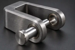
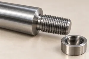
A press fit looks simple on a drawing: one shaft goes into one hole, and the two parts stay together through interference.
In real CNC machining, it is not that simple.
A press fit tolerance must control more than the nominal diameter. Hole size, shaft size, roundness, cylindricity, surface finish, coating thickness, material stiffness, temperature, inspection method, and assembly force can all decide whether the part assembles smoothly or fails during production.
For buyers, the real question is not only:
What tolerance should I use for a press fit?
The better question is:
Which features control the final interference, and when should they be inspected?
If the drawing only says “press fit” without defining the fit, material condition, surface finish, and inspection method, the supplier may machine a part that measures correctly in one way but fails during assembly.
What Is Press Fit Tolerance?
Press fit tolerance defines the controlled size relationship between a shaft and a hole when the shaft is intentionally larger than the hole, or when the final tolerance range creates interference after assembly.
The goal is to create enough holding force without damaging the parts.
A press fit is often used for:
| Application | Common Fit Risk |
|---|---|
| Bearing seats | Too loose may cause slip; too tight may damage the bearing |
| Bushings | Poor fit may affect alignment, wear, or service life |
| Pins and dowels | Wrong interference may affect location accuracy |
| Shaft-hub assemblies | Excessive force may crack the hub or distort the shaft |
| Inserts and sleeves | Surface finish and material stiffness may change assembly force |
| Precision fixtures | Fit must hold position without damaging datum surfaces |
For general tolerance planning, see our CNC machining tolerances guide. This article focuses specifically on press fit tolerance for CNC machined parts.
Press Fit, Transition Fit, and Clearance Fit
Not every shaft-and-hole pair should be a press fit. Before choosing a tolerance, the designer should decide what the assembly needs to do.
| Fit Type | Size Relationship | Typical Use |
| Clearance fit | Hole is larger than shaft | Moving parts, easy assembly, removable components |
| Transition fit | May have slight clearance or slight interference | Accurate location with moderate assembly force |
| Press fit / interference fit | Shaft is larger than hole in the final condition | Permanent or semi-permanent holding force |
A common mistake is choosing a press fit when a transition fit is enough. This can increase machining cost, inspection work, assembly force, and part damage risk.
Another mistake is choosing a clearance fit when the assembly actually needs holding force. In that case, the part may pass dimensional inspection but fail in vibration, rotation, or load.
The correct fit should come from the function, not from habit.
Why Press Fit Tolerance Is Not Just a Diameter Number
A press fit is controlled by two mating features, not one dimension.
Even if the shaft diameter is correct, the assembly may still fail if the hole is tapered, out-of-round, rough, coated, or measured before finishing.
A press fit should review:
| Factor | Why It Matters |
| Hole diameter | Controls available interference from the internal feature |
| Shaft diameter | Controls external feature size and insertion force |
| Roundness | A roundness issue can create local high spots or loose zones |
| Cylindricity | A tapered bore or shaft may assemble unevenly |
| Surface roughness | Peaks may increase assembly force or wear down during pressing |
| Coating thickness | Anodizing, plating, or passivation may change final size |
| Material stiffness | Aluminum, steel, brass, bronze, and plastics behave differently |
| Wall thickness | Thin hubs may expand, crack, or distort |
| Assembly temperature | Thermal expansion can change fit during pressing |
| Inspection timing | Before finishing and after finishing may not give the same result |
This is why press fit tolerance should be part of a design review, not just a dimension copied from an old drawing. For broader feature design and drawing notes, see our CNC machining design guide.
A press fit should be designed as a tolerance system, not as one tight number on one feature.
Another hidden risk is bushing bore closure. When a softer brass, bronze, or engineering plastic bushing is pressed into a more rigid metal housing, the interference force can reduce the bushing’s internal diameter after assembly. This means the bushing ID may be correct before pressing but too small after installation.
The amount of bore closure depends on OD interference, wall thickness, material stiffness, housing rigidity, lubrication, and press method. For this reason, a critical bushing ID should not always be accepted only by pre-press measurement. If the shaft running clearance is important, the drawing should clarify whether the ID is controlled after pressing, whether final sizing or reaming is required after installation, and which inspection method confirms the final bore.
Hole-Basis and Shaft-Basis Thinking
Many engineering drawings use a hole-basis system, where the hole is controlled to a standard range and the shaft tolerance is selected to create the required fit.
This is common because holes are often produced by drilling, boring, reaming, or grinding tools that are easier to standardize.
A simplified way to think about it:
| System | What Usually Stays More Standard | What Is Adjusted |
| Hole-basis fit | Hole tolerance zone | Shaft size and tolerance |
| Shaft-basis fit | Shaft tolerance zone | Hole size and tolerance |
For CNC buyers, the exact fit callout should come from the engineering requirement. A drawing may use ISO fit symbols such as H7/p6, H7/r6, or another fit class depending on load, size, material, and assembly method.
However, fit symbols alone may not be enough. A real press fit may still need notes for surface finish, coating, roundness, inspection, and assembly conditions.
Material Behavior Changes Press Fit Risk
The same interference value does not behave the same in every material.
A steel shaft pressed into an aluminum housing is not the same as a stainless shaft pressed into a stainless hub. A brass bushing does not behave like a hardened steel sleeve. An engineering plastic bore may creep or relax after assembly.
| Material Pair | Press Fit Concern |
| Steel shaft + aluminum housing | Aluminum may expand, deform, or lose holding force under heat |
| Stainless shaft + stainless bore | Higher assembly force and galling risk may need review |
| Brass or bronze bushing + steel bore | Softer material may deform during pressing |
| Aluminum shaft + aluminum bore | Surface damage and coating thickness may be important |
| Plastic bore + metal pin | Creep, relaxation, and moisture/temperature effects may change fit |
| Heat-treated stainless parts | Final size may change after heat treatment |
Stainless-on-stainless press fits need extra caution. When similar austenitic stainless steels are pressed together, such as a 304 shaft into a 304 bore or a 316 shaft into a 316 bore, high local pressure and sliding friction can increase the risk of galling. If the passive surface film breaks during assembly, fresh metal surfaces may adhere to each other and cause seizure, surface tearing, or a part that stops halfway through the press stroke.
To reduce this risk, the design review may consider a different material pairing, a different hardness condition, a controlled surface finish, a suitable assembly lubricant or anti-seize compound, and a carefully selected interference range. For example, a hardened or aged stainless shaft may behave differently from an annealed stainless mating bore, but the final choice should still match corrosion, strength, and inspection requirements. For heat-treated stainless material behavior, see our 17-4 PH stainless steel machining article.
A press fit should always be reviewed with material grade, heat treatment condition, wall thickness, and operating temperature.
Shafts, Pins, and Turned Features
Many press fit parts are turned components: pins, shafts, bushings, spacers, sleeves, bearing seats, and round inserts.
For these parts, diameter tolerance is important, but it is not the only control.
| Turned Feature | What to Review |
| Bearing seat | Diameter, roundness, runout, shoulder location |
| Press-fit pin | Diameter, chamfer, insertion end, surface finish |
| Sleeve or bushing | OD, ID, wall thickness, roundness after pressing |
| Shaft shoulder | Perpendicularity and seating face quality |
| Groove near press area | Stress concentration and assembly damage risk |
| Long shaft | Straightness, runout, and inspection support |
If the shaft is long, thin, or interrupted by grooves, the press fit may be affected by deflection or local diameter variation. For turned features, see our CNC turning parts guide for more shaft, shoulder, groove, and inspection considerations.
Surface Finish and Coating Can Change the Fit
Surface finish has a direct effect on press fit performance.
A rougher surface may increase insertion force at first, but the surface peaks may flatten during pressing. A very smooth surface may assemble more predictably, but it may also change friction behavior.
The drawing should define whether the press fit surface requires a specific roughness value.
| Surface Condition | Possible Effect |
| Rough bore | Higher assembly force, inconsistent contact |
| Rough shaft | Surface peaks may deform during pressing |
| Polished shaft | Lower friction but possible slip risk depending on design |
| Anodized aluminum | Coating buildup may reduce hole size or increase shaft size |
| Plated parts | Thickness may change final fit range |
| Passivated stainless | Usually smaller dimensional impact, but cleaning and surface condition still matter |
| Bead blasted surface | Texture may affect friction and cosmetic appearance |
Surface treatment should be planned before machining when the treated surface is part of the press fit. If coating or plating is applied after machining, the final size should be checked after finishing.
For surface treatment planning, roughness notes, coating effects, and finish selection, see our CNC surface finishes guide.
Burrs and Edge Break Around Press Fits
Burrs are one of the most common hidden problems in press fit assemblies.
A hole may measure correctly, but a raised burr around the entrance can scrape the shaft, increase insertion force, damage a coating, or prevent the part from seating fully.
A shaft may also have a burr or sharp edge that damages the bore during assembly.
| Feature | Burr Risk |
| Hole entrance | Raised burr may block insertion or scrape the shaft |
| Shaft end | Sharp edge may gouge the bore |
| Cross hole near fit area | Internal burr may interfere with assembly |
| Shoulder near bearing seat | Burr may prevent full seating |
| Groove near press zone | Burr may create local stress or damage seal |
| Coated edge | Deburring after coating may expose base material |
A controlled chamfer or edge break is often needed at the insertion side. But the chamfer should not remove functional bearing area unless the design allows it.
For burr control and drawing notes, see our what is deburring article.
Inspection Methods for Press Fit Features
A press fit cannot be controlled only by a quick caliper check.
For simple, low-risk parts, micrometers, bore gauges, plug gauges, or pin gauges may be enough. For high-risk features, roundness, runout, position, cylindricity, or CMM inspection may need review.
| Feature | Suggested Inspection Method |
| Shaft diameter | Micrometer, air gauge, or suitable diameter measurement |
| Bore diameter | Bore gauge, plug gauge, air gauge, or CMM depending on requirement |
| Bearing seat | Diameter, roundness, runout, and shoulder inspection |
| Thin wall bore | Check after unclamping if deformation risk exists |
| Coated press area | Inspect after coating or finishing |
| Critical assembly feature | Confirm final fit range and functional datum relationship |
| Batch production | Sampling plan or process control may be needed |
For high-risk press fit bores, the inspection plan should also consider roundness and lobing, not only diameter. A bore can measure within size at several two-point positions but still have an odd-lobed shape caused by chucking pressure, thin-wall deformation, vibration, or process instability.
This is especially important for bearing seats and precision sleeves. Hidden 3-lobe or 5-lobe geometry can create local pressure peaks after assembly, even when a simple diameter check looks acceptable. For tighter interference applications, the supplier may need to use a suitable bore gauge strategy, three-point internal measurement, V-block or roundness checks, CMM inspection, or profile scanning depending on the tolerance and risk level. The drawing should state when roundness, cylindricity, runout, or final assembled bore condition must be verified.
Temperature also matters. Measuring a precision fit in a hot shop and assembling it in a cooler environment can change the result. For tight fits, inspection temperature and part stabilization should be reviewed.
The inspection plan should match the function of the fit. If the part is safety-critical, high-load, high-speed, or difficult to replace, inspection should be defined before production.
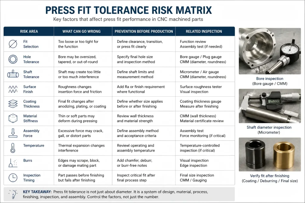
Press Fit Tolerance Risk Matrix
The table below shows why press fit tolerance should be reviewed as a full manufacturing system.
| Risk Area | What Can Go Wrong | Prevention Before Production |
| Fit selection | Too loose or too tight for the function | Define clearance, transition, or press fit clearly |
| Hole tolerance | Bore may be oversized, tapered, or out-of-round | Specify final hole size and inspection method |
| Shaft tolerance | Shaft may create too little or too much interference | Define shaft limits and measurement method |
| Surface finish | Roughness changes insertion force and friction | Add Ra or finish requirement where functional |
| Coating thickness | Final fit changes after anodizing, plating, or coating | Define whether size applies before or after finishing |
| Material stiffness | Thin or soft parts may deform during pressing | Review wall thickness and material strength |
| Assembly force | Excessive force may crack, gall, or distort parts | Define assembly method and acceptance criteria |
| Temperature | Thermal expansion changes interference | Review operating and assembly temperature |
| Burrs | Edges may scrape, block, or damage mating part | Add chamfer, deburr, or burr-free notes |
| Inspection timing | Part passes before finishing but fails after finishing | Inspect critical fit after final process step |
This table can be used as a checklist during DFM review or supplier quotation review.
Common Mistakes When Specifying Press Fit Tolerance
Most press fit problems start before machining. They start in unclear drawings and incomplete RFQs.
| Mistake | Possible Result |
| Only writing “press fit” on the drawing | Supplier does not know the required fit range |
| Tightening only the shaft tolerance | Hole variation still causes assembly failure |
| Ignoring roundness | Local high spots increase press force |
| Ignoring surface finish | Friction and seating behavior become inconsistent |
| Forgetting coating thickness | Final interference changes after finishing |
| Using the same fit for all materials | Soft or thin parts may deform |
| Ignoring bushing bore closure | ID may become too small after pressing |
| Pressing similar stainless steels without galling control | Parts may seize, tear, or stop during assembly |
| No chamfer or edge break note | Shaft or bore may be damaged during insertion |
| Inspecting before surface treatment only | Final assembly size may be wrong |
| Relying only on two-point diameter checks | Lobing or roundness errors may be missed |
| No assembly method defined | Cold pressing, thermal fitting, and manual assembly may give different results |
| No inspection report requested | Buyer may not receive the evidence needed for acceptance |
A good press fit drawing should make the assembly requirement clear before quotation.
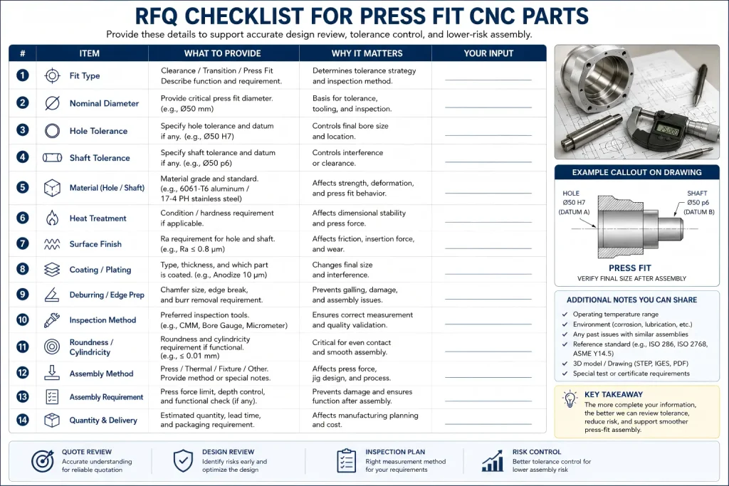
RFQ Checklist for Press Fit CNC Parts
Before sending a press fit part for quotation, prepare the key information that affects machining, finishing, inspection, and assembly.
If these items are missing, the quote may look simple, but the assembly risk is still undefined.
| RFQ Item | What to Provide | Why It Matters |
| Fit type | Clearance, transition, press fit, or ISO fit callout | Defines the assembly function |
| Nominal diameter | Hole and shaft nominal size | Sets the fit calculation baseline |
| Hole tolerance | Size limits or fit symbol | Controls internal feature size |
| Shaft tolerance | Size limits or fit symbol | Controls external feature size |
| Material grade | Shaft and mating part material | Affects stiffness, deformation, and assembly force |
| Heat treatment | Final material condition if required | May change final size or hardness |
| Surface finish | Ra value or functional surface note | Controls friction, seating, and wear |
| Coating or plating | Thickness, masking, final-size requirement | Prevents post-finish fit errors |
| Deburring note | Chamfer, edge break, burr-free areas | Protects assembly surfaces |
| Inspection method | Gauge, micrometer, bore gauge, CMM, report | Confirms final acceptance |
| Roundness or cylindricity requirement | Roundness, cylindricity, runout, or profile control if functional | Helps detect hidden lobing, taper, or local high spots |
| Assembly method | Cold press, thermal assembly, adhesive, retaining compound | Affects force and process planning |
| Quantity | Prototype, low-volume, or production | Affects fixture, inspection, and process control |
If the fit is critical, send both the 2D drawing and 3D model. The 2D drawing should control the tolerance, fit, surface finish, and inspection notes. The 3D model helps review geometry, tool access, wall thickness, and assembly direction.
How Rapid Efficient Supports Press Fit CNC Machined Parts
Rapid Efficient can review press fit CNC machined parts before quotation, including shaft and bore tolerances, material behavior, surface finish, coating allowance, deburring requirements, inspection method, and assembly risk.
For bearing seats, bushings, shafts, pins, sleeves, housings, and fitted inserts, we can help check whether the drawing clearly defines the final fit condition. We can also review whether critical dimensions should be inspected before or after coating, heat treatment, passivation, or other finishing steps.
If you are sourcing CNC machined parts with press fit features, send us your STEP file, 2D drawing, material requirement, fit notes, surface finish requirement, coating requirement, quantity, and inspection expectations. Our team can review the machining and delivery requirements before quotation.
FAQ
What is press fit tolerance?
Press fit tolerance is the controlled size relationship between a shaft and hole that creates interference after assembly. It should define both mating features, not just one diameter.
Is press fit the same as interference fit?
A press fit is a type of interference fit. In many buyer discussions, the two terms are used closely, but the required fit range and assembly method should still be defined clearly on the drawing.
Should I tolerance the hole or the shaft for a press fit?
Both matter. Many designs use a hole-basis fit, where the hole follows a standard tolerance zone and the shaft is adjusted to create the required interference. But the correct approach depends on the part function, material, and manufacturing route.
Can a bushing ID change after press fitting?
Yes. A softer bushing can experience bore closure after it is pressed into a housing. If the internal diameter controls running clearance, the drawing should clarify whether the ID is inspected after pressing or whether final sizing is required after installation.
Can stainless steel press fits gall during assembly?
Yes. Stainless-on-stainless press fits can increase galling risk, especially when similar austenitic stainless grades slide under high pressure. Material pairing, hardness condition, lubrication, surface finish, and interference range should be reviewed before assembly.
Can surface finish affect press fit?
Yes. Surface roughness affects friction, insertion force, seating behavior, and wear. Coating or plating can also change the final size of the press fit feature.
Can anodizing or plating change press fit tolerance?
Yes. Anodizing, plating, and other coatings can change the final hole or shaft size. Critical press fit dimensions should define whether the tolerance applies before or after finishing.
What inspection method is best for press fit parts?
It depends on the feature. Shafts may be checked with micrometers or air gauges. Bores may need bore gauges, plug gauges, CMM inspection, or roundness checks. High-risk press fit features may also need roundness, runout, cylindricity, or profile review.
Why can a bore pass diameter inspection but still fail assembly?
A bore may measure correctly at several two-point positions but still have lobing, taper, or roundness error. These hidden shape errors can create local pressure peaks during assembly, especially for bearings and precision sleeves.
What should I include in a press fit RFQ?
Include the fit type, nominal size, hole tolerance, shaft tolerance, material grade, heat treatment, surface finish, coating requirement, deburring notes, inspection method, roundness or cylindricity requirement if functional, assembly method, quantity, and delivery requirement.