Flatness looks simple on a drawing, but it can become one of the most misunderstood requirements in CNC machining.
A buyer may write “flatness 0.05 mm” and expect a sealing face, mounting plate, rail surface, or thin machined panel to assemble perfectly. The supplier may read the same note as a general form requirement on one surface. Both sides may think the drawing is clear, but the inspection result can still become disputed after machining, finishing, or assembly.
The problem becomes even more important when a drawing says:
Flatness 0.05 mm per 100 mm
or:
Flatness 0.1 mm / 300 mm
This is not the same as saying the entire surface must be flat within 0.05 mm or 0.1 mm. A per-unit-length flatness requirement controls local form over a defined inspection window. It may be used when a long or large surface needs local contact quality, but the full part may still have a different overall flatness requirement.
For CNC buyers, the real question is not only:
How flat can you machine this part?
The better question is:
Which surface must be flat, over what length, after which process, and by which inspection method?
Without that clarity, a part may pass one inspection method but fail during assembly.
What Is Flatness Tolerance?
Flatness tolerance controls how much a surface may deviate from an ideal flat plane. In GD&T, flatness is a form control applied to a surface. It does not require a datum when it is controlling that surface by itself.
In practical terms, the surface must lie within a tolerance zone between two parallel planes separated by the flatness value.
For example:
| Drawing Note | Practical Meaning |
|---|---|
| Flatness 0.05 mm | The controlled surface should remain within a 0.05 mm flatness zone |
| Flatness 0.1 mm | The controlled surface has a wider allowed form variation |
| Flatness 0.05 mm per 100 mm | Local flatness is controlled within each 100 mm inspection length |
| Flatness 0.05 mm after anodizing | The requirement applies after the surface treatment, not only after machining |
For general tolerance planning, see our CNC machining tolerances guide. This article focuses specifically on flatness tolerance per unit length and how it affects CNC machined parts.
Why Flatness Per Unit Length Is Different from Overall Flatness
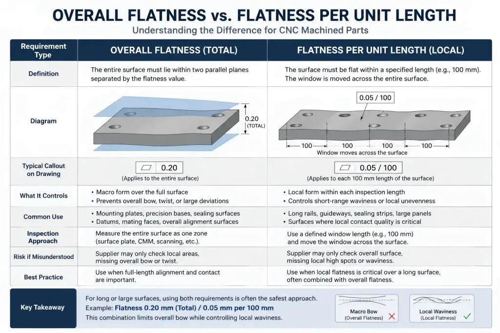
Overall flatness and flatness per unit length are not the same requirement.
Overall flatness controls the full surface as one feature. Flatness per unit length controls local flatness over a defined length or window.
A long surface may be locally smooth but slightly bowed over its full length. Another surface may have good overall flatness but local waviness that affects sealing, bearing support, or assembly contact.
| Requirement Type | What It Controls | Common Use |
| Overall flatness | Full surface form over the entire controlled area | Mounting plates, datum surfaces, sealing faces, precision bases |
| Flatness per unit length | Local form over a defined inspection length | Long rails, long sealing strips, sliding surfaces, large plates |
| Parallelism | Orientation of one surface relative to a datum | Mating faces that must stay aligned to another surface |
| Profile of a surface | Shape and location of a surface relative to datums | Complex contours, castings, molded shapes, multi-datum surfaces |
If the drawing only says “flatness 0.05,” the supplier may inspect the entire surface as one zone. If the drawing says “flatness 0.05 per 100 mm,” the inspection logic changes. The surface may need to be checked in local sections.
A common engineering trap is assuming that flatness per unit length automatically controls the full part shape. It does not always do that. A long guide rail, sealing strip, or mounting surface may meet a local requirement such as 0.05 mm per 100 mm, while still showing a gradual bow over the full length.
This is why long parts often need both local and overall controls. The local value helps limit short-range waviness, while the overall value helps prevent macro-bending across the entire surface. For example, a drawing may need to define both overall flatness and flatness per 100 mm when the surface must support both local contact and full-length alignment.
Without this distinction, the supplier may inspect each local section correctly, but the assembled part may still show poor contact, sliding resistance, gasket leakage, or alignment error across the full span.
This matters because machining, clamping, heat, surface finishing, and inspection method can all influence the result.
A drawing should make clear whether the supplier must control the whole surface, each local section, or both.
Where Flatness Tolerance Matters in CNC Machining
Flatness is not equally important on every face of a CNC machined part. It becomes important when the surface controls assembly, sealing, alignment, movement, or measurement.
| Part Feature | Why Flatness Matters |
| Sealing face | Poor flatness may cause leakage or uneven gasket compression |
| Bearing mounting face | Local high spots may distort the bearing or reduce support |
| Rail or guide surface | Waviness may affect sliding, alignment, or wear |
| Thin machined plate | Stress release may create bowing after machining |
| Fixture base | Poor contact may affect repeatability |
| Heat sink base | Flatness affects contact area and thermal transfer |
| Sensor mounting surface | Tilt or local unevenness may affect measurement accuracy |
| Press-fit housing face | Flatness near the bore may affect seating and alignment |
For press-fit and bearing-related features, flatness should be reviewed together with hole size, roundness, shaft fit, and assembly method. See our press fit tolerance article for more shaft-and-bore fit risks.
Why CNC Parts Lose Flatness
A surface can lose flatness even when the CNC program is correct.
Flatness is affected by the whole manufacturing route, not only by the final toolpath.
Common causes include:
| Cause | How It Affects Flatness |
| Residual stress in raw material | Part moves after material is removed |
| Uneven stock removal | One side releases stress more than the other |
| Excessive clamping force | Surface springs back after unclamping |
| Thin wall or thin plate geometry | Low stiffness allows bending during cutting |
| Heat during machining | Thermal expansion changes shape during inspection |
| Poor support during machining | Large surfaces sag or vibrate |
| Aggressive roughing | Cutting force distorts thin features |
| Surface finishing after machining | Grinding, polishing, blasting, coating, or anodizing may change final condition |
| Packaging or handling | Large thin parts may bend after inspection |
This is why flatness should be treated as a process requirement, not just a final drawing note.
For broader design and machining risk review, see our CNC machining design guide.
Material and Thickness Change Flatness Risk
The same flatness tolerance does not carry the same risk in every material.
A thick steel block, a thin aluminum plate, a copper busbar, and a plastic housing will not behave the same way after machining.
| Material / Geometry | Flatness Risk |
| Thin aluminum plate | May bow after pocketing or one-sided machining |
| Large 6061 or 7075 plate | Stock condition and stress relief should be reviewed |
| Stainless steel plate | Higher cutting forces and heat may affect stability |
| Copper or brass plate | Soft material may smear, burr, or deform under clamping |
| Engineering plastic sheet | Moisture, temperature, and clamping can change shape |
| Cast or forged blank | Internal stress and skin removal may create movement |
| Heat-treated part | Final flatness may change after thermal processing |
Thickness also matters. A 10 mm thick plate and a 2 mm thin panel with the same flatness callout do not have the same manufacturing risk.
If flatness is functional, the RFQ should include material grade, stock form, thickness, machining side, surface finish, final condition, and inspection requirement. For material-related machining behavior, see our CNC machining materials guide.
Machining Strategy for Flatness-Critical Parts
Flatness-critical parts often require a different machining strategy from ordinary block machining.
A practical route may include:
| Process Step | Why It Helps |
| Review raw stock condition | Reduces risk from warped or stressed material |
| Rough both sides | Balances stress release where possible |
| Leave finishing allowance | Allows correction after roughing movement |
| Flip and re-clamp carefully | Reduces one-sided stress and clamping distortion |
| Use broad support | Prevents sagging or local deformation |
| Control clamping force | Avoids machining a distorted shape |
| Use finishing passes | Reduces cutting force on final surface |
| Allow rest time when needed | Lets stress movement settle before final machining |
| Verify free-state flatness after unclamping | Thin plates may appear flat while held by vacuum chucks, magnetic fixtures, or strong clamps, then spring back after release. Final inspection should confirm the relaxed condition when free-state flatness matters. |
| Confirm after finishing | Checks the final condition that the customer receives |
For thin plates and large flat surfaces, workholding can create a false sense of flatness. A vacuum chuck, magnetic fixture, or heavy clamp may force the part flat during machining, but the part may recover some of its original distortion after the holding force is released.
For flatness-critical parts, the process route may need light finishing cuts, balanced stock removal, controlled clamping, suitable support, rest time between roughing and finishing, or final inspection after unclamping. The goal is not only to machine a flat surface while restrained, but to confirm the surface condition that the customer will actually receive.
Not every project needs all of these steps. A small rigid block may need only ordinary setup and final inspection. A large thin plate may require a more careful route.
The important point is that flatness should be quoted with the process route in mind.
Surface Finish and Flatness Are Related but Not the Same
A smooth surface is not automatically flat.
A flat surface is not automatically smooth.
Surface finish controls texture, roughness, tool marks, and local surface quality. Flatness controls form over a larger surface area or inspection window.
Both may matter on sealing faces, sliding surfaces, bearing seats, and precision mounting faces.
| Requirement | Controls | Typical Inspection |
| Flatness | Overall or local surface form | Surface plate, CMM, height gauge, scanning, straightedge method depending on requirement |
| Surface roughness | Micro-texture of the surface | Roughness tester |
| Parallelism | Orientation relative to a datum | CMM, height gauge, fixture-based inspection |
| Profile | Surface form and location relative to datums | CMM or scanning method |
| Cosmetic finish | Visual appearance | Visual inspection and agreed sample |
A sealing face may require both flatness and roughness. A heat sink base may need controlled flatness for contact area and a suitable surface finish for thermal interface material. A sliding surface may require flatness, roughness, and material compatibility.
For surface treatment planning, roughness notes, bead blasting, polishing, anodizing, and other finishing effects, see our CNC surface finishes guide.
Inspection Methods for Flatness Tolerance
Flatness inspection depends on surface size, tolerance value, part stiffness, and drawing requirement.
A quick caliper check cannot verify flatness.
Common inspection methods include:
| Inspection Method | Suitable For | Limitation |
| Surface plate + height gauge | Many machined faces and plates | Requires stable support and clear measuring points |
| Straightedge + feeler gauge | Basic shop check for larger surfaces | Limited resolution and operator-dependent |
| CMM point measurement | Datum-related features and documented reports | Point spacing and support condition affect result |
| CMM scanning | More detailed surface map | More time and cost |
| Optical or laser scanning | Large or complex surfaces | Method and accuracy should be confirmed |
| Functional assembly test | Sealing or contact surfaces | Does not replace dimensional inspection when reports are required |
| Flatness gauge or custom fixture | Repeat production checks | Fixture design must match the real function |
For flatness per unit length, the inspection plan should also define how the local window is moved across the surface. If the inspector only checks non-overlapping sections, such as 0–100 mm, 100–200 mm, and 200–300 mm, a local high spot or waviness near the boundary between sections may be missed.
For high-risk sealing faces, sliding surfaces, long rails, or precision mounting areas, an overlapping measurement pattern may be safer. A 50% overlapping grid, continuous CMM scan, or agreed measurement map can help catch local waviness that a sparse point check may overlook.
The drawing does not always need to define every measurement point, but when flatness is critical, the RFQ should clarify whether the supplier needs a basic shop check, documented point grid, CMM report, surface map, or functional contact inspection.
For quality-related inspection planning, see our quality assurance page.
The inspection plan should define:
| Inspection Detail | Why It Matters |
| Measurement surface | Prevents checking the wrong face |
| Overall flatness or per-unit flatness | Avoids interpretation disputes |
| Inspection window length | Defines how local flatness is checked |
| Support method | Thin parts may bend under their own weight |
| Free state or restrained state | Clamped parts may appear flatter than free parts |
| Measurement grid | Sparse points may miss local waviness |
| Inspection timing | Before and after finishing may not match |
| Report requirement | Confirms whether values must be documented |
If a surface is critical, the buyer should not simply write “flatness required.” The drawing should state the flatness value, whether it is overall or per unit length, the controlled surface, and the final process condition.
Flatness Tolerance Risk Matrix
The table below shows why flatness tolerance should be reviewed as a full manufacturing and inspection system.
| Risk Area | What Can Go Wrong | Prevention Before Production |
| Requirement type | Supplier may confuse overall flatness with per-unit flatness | Define overall flatness, local flatness, or both |
| Surface selection | Wrong face may be inspected | Mark the controlled surface clearly |
| Material stress | Part may bow after machining | Review stock form, machining sequence, and finishing allowance |
| Thin wall design | Surface may flex during cutting or inspection | Review wall thickness, support, and clamping plan |
| Clamping | Part may be machined flat only while restrained | Inspect after unclamping when free-state flatness matters |
| Surface finish | Polishing, blasting, or coating may alter the final surface | Define whether flatness applies before or after finishing |
| Inspection grid | Local waviness may be missed | Define measurement spacing or inspection method when critical |
| Per-unit window | Different inspectors may use different window lengths | Specify the unit length clearly |
| Datum relationship | Flatness may not control orientation to another surface | Use parallelism or profile when datum relationship matters |
| Packaging | Thin parts may bend after inspection | Review protection and handling for large flat surfaces |
This matrix is useful during DFM review and supplier quotation review.
Common Mistakes When Specifying Flatness Tolerance
Most flatness problems begin with unclear drawings.
| Mistake | Possible Result |
| Writing only “keep flat” | Supplier does not know the tolerance value |
| Writing flatness without surface identification | Wrong face may be controlled |
| Confusing flatness with parallelism | Surface may be flat but not aligned to a datum |
| Using per-unit flatness without window length | Inspection method becomes unclear |
| Using per-unit flatness without an overall limit when full-length alignment matters | Local sections may pass while the full surface still bows |
| Requiring tight flatness on thin walls | Cost rises and result may still be unstable |
| Ignoring raw material stress | Part moves after rough machining |
| Inspecting while clamped | Free-state part may fail after removal |
| Forgetting surface treatment | Final flatness may change after coating or polishing |
| Using too few inspection points | Local waviness may be missed |
| Checking only non-overlapping windows | Boundary waviness may be missed |
| Not defining final inspection timing | Supplier may inspect before the final process |
| Applying tight flatness to non-functional cosmetic faces | Cost increases without improving assembly |
| No report requirement | Buyer may not receive documented evidence |
A good flatness requirement tells the supplier what surface must function, when it must be checked, and how the result should be verified.
RFQ Checklist for Flatness-Critical CNC Parts
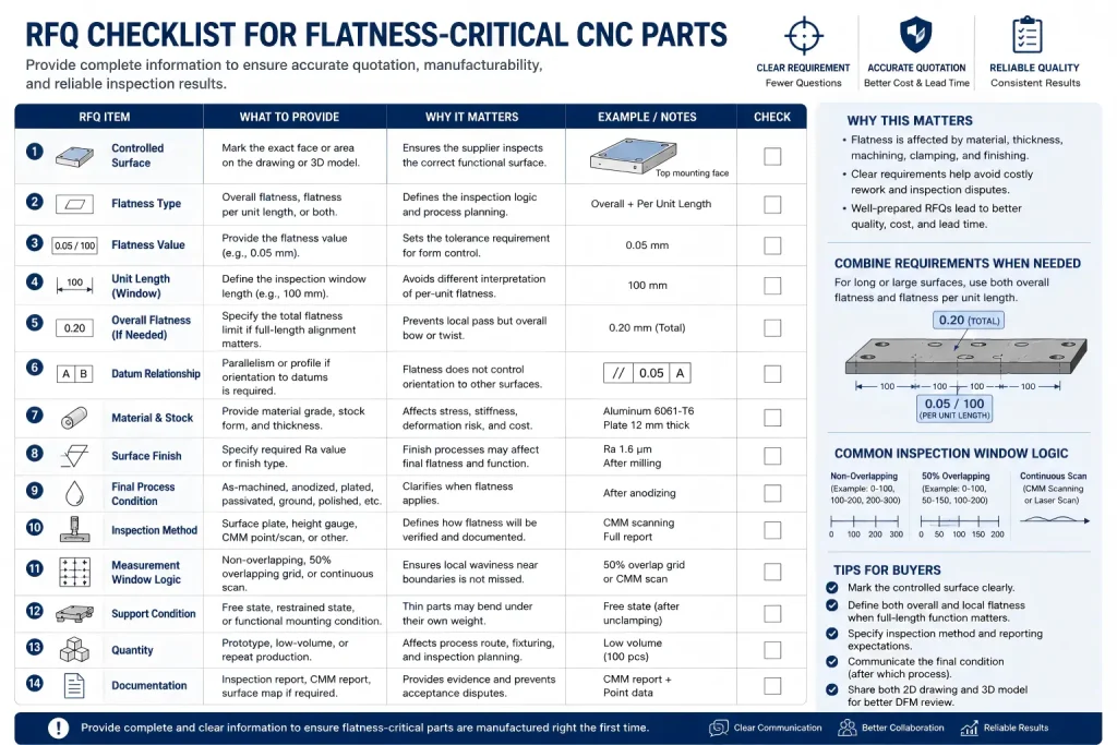
Before sending a flatness-critical part for quotation, prepare the information that affects machining, finishing, inspection, and cost.
| RFQ Item | What to Provide | Why It Matters |
| Controlled surface | Mark the exact face or area | Prevents inspection of the wrong surface |
| Flatness type | Overall flatness, flatness per unit length, or both | Defines the inspection logic |
| Flatness value | Example: 0.05 mm or 0.05 mm / 100 mm | Sets the tolerance requirement |
| Overall limit | Total flatness limit if full-length alignment matters | Prevents local pass / full-length fail disputes |
| Unit length | The local inspection window if required | Avoids different interpretation |
| Measurement window logic | Non-overlapping points, overlapping grid, CMM scan, or agreed map | Clarifies how local flatness is verified |
| Datum relationship | Parallelism or profile if orientation matters | Flatness alone does not control datum alignment |
| Material grade | Aluminum, stainless steel, copper, plastic, etc. | Affects stress, stiffness, and machining route |
| Stock form and thickness | Plate, bar, casting, extrusion, sheet | Affects deformation risk |
| Machined side | One side, both sides, pocketed side, sealing side | Influences stress release and support |
| Surface finish | Ra value, machining marks, polishing, blasting, coating | Can affect final contact and inspection |
| Final process condition | As-machined, anodized, plated, passivated, ground, polished | Clarifies when flatness applies |
| Inspection method | Surface plate, height gauge, CMM, scanning, report | Defines how flatness will be verified |
| Support condition | Free state, restrained state, functional mounting condition | Critical for thin or flexible parts |
| Quantity | Prototype, low-volume, repeat production | Affects fixture and inspection planning |
| Documentation | Inspection report, CMM report, surface map if required | Prevents acceptance disputes |
If the flatness requirement is critical, send both the 2D drawing and 3D model. The 2D drawing should define the tolerance, controlled surface, datum relationship, finish, and inspection notes. The 3D model helps review geometry, wall thickness, machining access, and support strategy.
How Rapid Efficient Supports Flatness-Critical CNC Parts
Rapid Efficient can review flatness-critical CNC machined parts before quotation, including material grade, part thickness, machining sequence, clamping risk, surface finish, post-processing, inspection method, and documentation requirements.
For plates, housings, sealing faces, mounting bases, bearing pads, fixture surfaces, and long machined rails, we can help check whether the drawing clearly defines overall flatness, flatness per unit length, final inspection condition, and any related datum requirements.
If you are sourcing CNC machined parts with flatness-sensitive surfaces, send us your STEP file, 2D drawing, material requirement, flatness notes, surface finish requirement, finishing requirement, quantity, and inspection expectations. Our team can review the machining and delivery requirements before quotation.
FAQ
What is flatness tolerance per unit length?
Flatness tolerance per unit length controls local flatness over a defined inspection length, such as 0.05 mm per 100 mm. It is different from overall flatness, which controls the full surface as one feature.
Is flatness per unit length enough for a long rail or plate?
Not always. A long part may meet local flatness per unit length while still having a gradual bow over the full span. If full-length alignment matters, the drawing should define both local flatness and an overall flatness limit.
Is flatness the same as parallelism?
No. Flatness controls the form of a surface by itself. Parallelism controls the orientation of one surface relative to a datum. A surface can be flat but still not parallel to another surface.
Does flatness need a datum?
Surface flatness by itself usually does not need a datum because it controls the form of the surface itself. If the surface must be aligned to another surface or datum, parallelism or profile may need review.
Can CNC machining hold tight flatness on thin plates?
It depends on material, thickness, size, stock condition, machining sequence, clamping, and inspection method. Thin plates can move after roughing or unclamping, so the process route should be reviewed before quotation.
Why should flatness be checked after unclamping?
A part may appear flat while held by strong clamps, a vacuum chuck, or a magnetic fixture. After the holding force is released, thin or stressed parts may spring back. If free-state flatness matters, inspection should confirm the relaxed condition.
Should flatness be inspected before or after surface finishing?
If the finished surface controls assembly, sealing, sliding, or contact, flatness should usually be confirmed after the final relevant process. The drawing should state whether the requirement applies before or after finishing.
Can surface finish affect flatness?
Surface finish and flatness are different requirements, but finishing processes such as grinding, polishing, bead blasting, coating, or anodizing can affect the final surface condition. Critical surfaces should define both flatness and finish requirements when needed.
What inspection method is best for flatness?
It depends on tolerance, surface size, part stiffness, and documentation needs. Surface plate checks, height gauges, CMM inspection, scanning, and functional checks may all be used depending on the requirement.
Why can sparse flatness inspection miss local waviness?
Sparse or non-overlapping measurement points may miss local high spots near inspection window boundaries. For high-risk sealing, sliding, or long alignment surfaces, an overlapping grid, CMM scan, or agreed measurement map may be needed.
What should I include in a flatness-critical RFQ?
Include the controlled surface, flatness value, whether the requirement is overall or per unit length, material grade, thickness, surface finish, final process condition, inspection method, support condition, quantity, and report requirement if needed.