A small tolerance note can change how a CNC part is machined, inspected, and accepted.
For example, these two drawing notes look similar:
50.00 ±0.05 mm
and:
50.00 +0.10 / -0.00 mm
Both control size, but they do not tell the machinist the same thing. One allows variation on both sides of the nominal size. The other keeps the part on one side of the nominal size.
For buyers, this matters when a part must fit into another part, hold a bearing, leave clearance, avoid interference, or stay within a final size after coating.
The main question is not only:
What tolerance value should I use?
The better question is:
Which direction can the size safely move without hurting assembly?
The Main Difference in One Sentence
Bilateral tolerance allows the dimension to vary in both directions from the nominal size. Unilateral tolerance allows the dimension to vary in only one direction from the nominal size.
For a CNC buyer, the important point is simple: the tolerance style should match the function of the feature. If both larger and smaller variation are acceptable, bilateral tolerance is often easier to read. If only one direction is safe for fit, clearance, or coating, unilateral tolerance may be clearer.
What Bilateral Tolerance Means
A bilateral tolerance allows variation above and below the nominal dimension.
Example:
50.00 ±0.05 mm
This means the finished size can be:
| Item | Value |
|---|---|
| Nominal size | 50.00 mm |
| Upper limit | 50.05 mm |
| Lower limit | 49.95 mm |
| Total tolerance | 0.10 mm |
This type of tolerance is common because it is easy to read. The nominal size sits in the middle of the tolerance zone.
Bilateral tolerance is useful when the part can still work if the feature is slightly larger or slightly smaller.
What Unilateral Tolerance Means
A unilateral tolerance keeps variation on one side of the nominal dimension.
Example:
50.00 +0.10 / -0.00 mm
This means the finished size can be:
| Item | Value |
| Nominal size | 50.00 mm |
| Upper limit | 50.10 mm |
| Lower limit | 50.00 mm |
| Total tolerance | 0.10 mm |
The part may be larger than 50.00 mm, but it should not be smaller than 50.00 mm.
Another example:
50.00 +0.00 / -0.10 mm
This means the finished size can be between 49.90 mm and 50.00 mm. The part may be smaller, but it should not be larger.
Unilateral tolerance is useful when the direction of variation matters. This often happens with fits, clearances, sealing surfaces, coating allowance, or mating parts.
The Same Size Limits Can Be Written in Different Ways
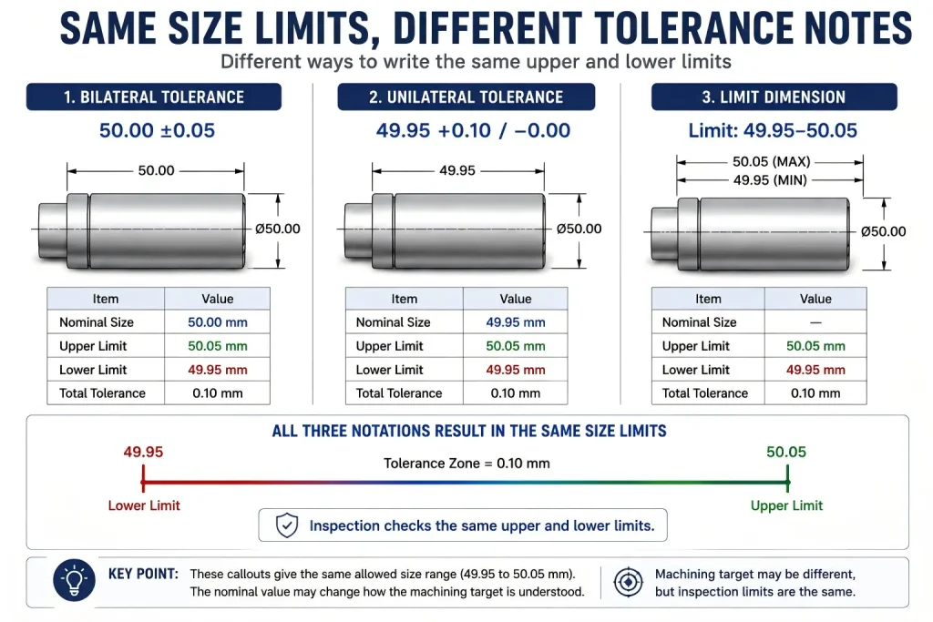
Sometimes two tolerance notes give the same upper and lower limits, even if they look different.
Example A:
50.00 ±0.05 mm
Limits:
| Limit | Value |
| Upper limit | 50.05 mm |
| Lower limit | 49.95 mm |
Example B:
49.95 +0.10 / -0.00 mm
Limits:
| Limit | Value |
| Upper limit | 50.05 mm |
| Lower limit | 49.95 mm |
Both examples allow the same final size range. But they may guide machining and inspection differently because the nominal value is written differently.
For buyers, the limit values matter more than the visual style of the note. A supplier will usually inspect the finished part against the upper and lower limits, not only against the nominal number.
The two callouts may look different, but the upper and lower limits are what inspection will finally check.
When Bilateral Tolerance Is Usually Better
Bilateral tolerance is often a good choice when the nominal size is the intended target and small variation on either side is acceptable.
Common examples include:
| Feature | Why Bilateral Tolerance May Work |
| General outside dimensions | Slightly larger or smaller size may still be acceptable |
| Non-critical pockets | Function does not depend on one-sided fit |
| Cosmetic cover size | Small variation on either side may not affect assembly |
| General machined surfaces | The nominal size is a practical machining target |
| Features controlled mainly by appearance | Function is not highly direction-sensitive |
| Prototype parts | Buyer wants a clear, simple tolerance for review |
Bilateral tolerance is easy for buyers, machinists, and inspectors to understand. It also avoids over-directing the process when one-sided control is not needed.
Use bilateral tolerance when the feature has room to vary in both directions without creating a fit or assembly problem.
When Unilateral Tolerance Is Usually Better
Unilateral tolerance is better when the part can only move safely in one direction.
For example, a shaft may need to stay below a maximum size so it can slide into a bore. A bore may need to stay above a minimum size so a pin can fit. A coated surface may need extra allowance because material will be added later.
Common examples include:
| Feature | Why Unilateral Tolerance May Help |
| Clearance holes | Hole should not become too small |
| Shafts for sliding fit | Shaft should not become too large |
| Bearing bores | Bore size may need a clear minimum or maximum |
| Press-fit features | Fit direction and assembly force matter |
| Coated or plated surfaces | Final size may change after finishing |
| Sealing grooves | Too much variation in one direction may affect sealing |
| Mating covers or slots | Clearance may be more important than equal variation |
| Datum-related contact faces | One side of variation may affect assembly stack-up |
Use unilateral tolerance when one direction is risky. The drawing should make clear whether the danger is being too large, too small, too tight, too loose, or out of final size after finishing.
How Tolerance Style Changes Machining Behavior
A machinist does not only look at the tolerance width. The written nominal value also affects how the feature is targeted during machining.
If the drawing says:
50.00 ±0.05 mm
the natural machining target is close to 50.00 mm.
If the drawing says:
50.00 +0.10 / -0.00 mm
the natural target may be slightly above 50.00 mm, because going below 50.00 mm would fail the drawing.
This does not mean unilateral tolerance is bad. It means the buyer should use it when the one-sided direction is intentional.
| Drawing Style | How It May Be Read in Production |
| 50.00 ±0.05 | Target near 50.00 mm |
| 50.00 +0.10 / -0.00 | Stay at or above 50.00 mm |
| 50.00 +0.00 / -0.10 | Stay at or below 50.00 mm |
| 49.95 +0.10 / -0.00 | Same limits as 50.00 ±0.05, but different nominal target |
| Limit dimension 49.95–50.05 | Directly shows allowed final range |
In production, the machining target is often set near the middle of the allowed size range, not always exactly on the written nominal size. For example, a dimension written as 50.00 +0.10 / -0.00 mm has a usable range from 50.00 mm to 50.10 mm, so the practical target may be around 50.05 mm.
This helps the shop keep the process away from the reject limits. It also gives some room for normal tool wear, machine drift, or small offset changes during production. For repeat orders, the supplier may monitor measured sizes and adjust offsets before the parts move too close to the upper or lower limit.
This is why the written tolerance style should match the real function. If the buyer wants the part centered around a true nominal size, bilateral tolerance may be clearer. If the buyer wants the part kept safely above or below a limit, unilateral tolerance may be a better choice.
For CNC parts, unclear tolerance direction can lead to parts that technically pass the drawing but feel wrong during assembly. This is why the tolerance note should match the real fit condition.
For broader tolerance planning, see our CNC machining tolerances guide.
Fit Examples Buyers Should Check
Tolerance direction matters most when the feature touches or fits with another part.
| Example | Safer Tolerance Thinking |
| Shaft sliding into a bore | Prevent the shaft from becoming too large |
| Pin going into a hole | Prevent the hole from becoming too small |
| Cover fitting into a slot | Control clearance direction |
| Bearing pressed into housing | Review bore size, roundness, and press-fit force |
| Coated aluminum part | Confirm whether size is before or after finishing |
| Threaded feature | Check whether plating, anodizing, or coating affects fit |
| Sealing groove | Review groove width, depth, and compression direction |
| Stacked assembly | Check how tolerance direction adds up across parts |
A bilateral tolerance may be fine for a general dimension, but a mating feature may need one-sided control. If assembly fit matters, the drawing should show the part’s functional direction clearly.
Tolerance direction also affects assembly stack-up. If several parts in an assembly all use one-sided tolerances in the same direction, the final assembly may shift toward one end of the allowed range.
This does not mean unilateral tolerance is wrong. It means the designer should check how the allowed size directions add together across the assembly. A single unilateral tolerance may be useful for one feature, but several unilateral tolerances in a stack can create tight assembly, loose fit, poor alignment, or unexpected clearance.
For multi-part housings, rails, brackets, covers, or precision tracks, buyers should review whether each tolerance direction supports the final assembly. If the stack-up becomes too risky, the drawing may need clearer datums, limit dimensions, adjusted nominal sizes, or a separate tolerance stack-up review.
For press-fit features, see our press fit tolerance article.
Coating and Surface Finish Can Change the Final Size
A dimension may be correct after machining but wrong after finishing.
Anodizing, plating, coating, polishing, and bead blasting can all affect final part condition in different ways. Some finishes add thickness. Some change the surface texture. Some affect only selected areas.
For this reason, the drawing should state whether the tolerance applies:
| Timing | Meaning |
| Before finishing | Machined size is checked before coating or surface treatment |
| After finishing | Final delivered size must meet tolerance |
| Masked area | Finish should not be applied to that feature |
| Selected surface only | Only marked surfaces receive the finish |
| Supplier review | Finishing and tolerance need to be checked together |
If a dimension controls fit, sealing, sliding, or electrical contact, do not assume the tolerance timing is obvious. State whether the final size is before or after finishing.
For design review around tolerance, finishing, and protected areas, see our CNC machining design guide.
Inspection Should Follow the Limits, Not the Guess
Inspection should confirm the upper and lower limits shown on the drawing. It should not depend on guessing what the designer “probably meant.”
For simple dimensions, calipers, micrometers, height gauges, bore gauges, pins, or thread gauges may be enough. For more complex features, CMM inspection may be needed.
| Inspection Point | Why It Matters |
| Upper limit | Confirms the part is not too large |
| Lower limit | Confirms the part is not too small |
| Final condition | Confirms whether the check is before or after finishing |
| Mating feature | Confirms whether fit direction is correct |
| Gauge method | Helps avoid disputes on holes, threads, and bores |
| Critical dimension report | Documents acceptance for important features |
| Batch consistency | Checks whether production stays centered or drifts toward one limit |
For high-precision or repeat-production parts, the quality report should also use the correct inspection target. Unilateral or unequal bilateral tolerances can cause confusion if the report software compares every result only against the written nominal value.
For example, a feature written as 50.00 +0.10 / -0.00 mm may be intentionally produced near 50.05 mm, because that is the middle of the allowed range. If a report treats 50.00 mm as the ideal target without explaining the tolerance range, the process may look shifted even when the parts are acceptable.
When Cp, Cpk, or other process capability data is required, the buyer and supplier should agree how the target, upper limit, and lower limit will be used in the report. This helps prevent disputes where the parts pass the drawing limits, but the quality report appears confusing because the target was not set correctly.
If the tolerance is unilateral, the inspector should pay close attention to the restricted side. A small drift in the wrong direction can reject the part even if the total tolerance range looks wide.
For inspection planning and reports, see our quality assurance page.
Buyer Drawing Checks Before Sending an RFQ
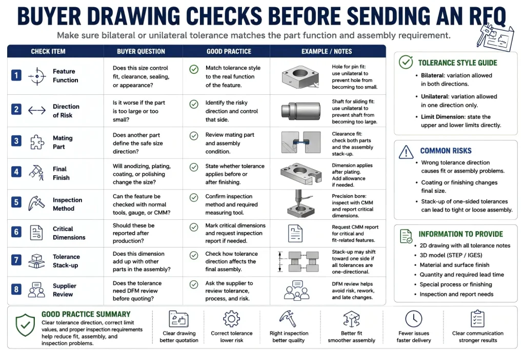
Before sending a CNC drawing for quotation, check whether the tolerance style matches the part’s function.
| Drawing Check | Buyer Question |
| Feature function | Does this size control fit, clearance, sealing, or appearance? |
| Direction of risk | Is it worse if the part is too large or too small? |
| Mating part | Does another part define the safe size direction? |
| Final finish | Will anodizing, plating, coating, or polishing change the size? |
| Inspection method | Can the feature be checked with normal tools, gauge, or CMM? |
| Critical dimensions | Should these be reported after production? |
| Tolerance stack-up | Does this dimension add up with other parts in the assembly? |
| Supplier review | Does the tolerance need DFM review before quoting? |
The goal is not to use the most complex tolerance style, but to make the part function clear before machining starts.
For assemblies where several tolerances add together, see our tolerance stack-up guide.
Simple Examples
Example 1: General Plate Width
Drawing note:
100.00 ±0.10 mm
This is a typical bilateral tolerance. The part may be slightly larger or smaller. If the width is not a tight fit feature, this may be clear enough.
Example 2: Shaft for Clearance Fit
Drawing note:
Ø10.00 +0.00 / -0.03 mm
This keeps the shaft from becoming larger than 10.00 mm. It may be useful when the shaft must fit into a mating hole.
Example 3: Hole That Must Not Be Too Small
Drawing note:
Ø6.00 +0.05 / -0.00 mm
This keeps the hole from becoming smaller than 6.00 mm. It may help when a pin, screw, or dowel must pass through the hole.
Example 4: Feature After Plating
Drawing note:
Ø12.00 +0.00 / -0.02 mm after plating
This tells the supplier that the final plated condition matters. Without that note, the part may be machined correctly but fail after plating thickness changes the final size.
Rapid Efficient Support for CNC Drawing Tolerance Review
Rapid Efficient can review CNC part drawings before quotation, including bilateral tolerance, unilateral tolerance, limit dimensions, fit direction, coating allowance, inspection method, and critical dimension reporting.
For aluminum, stainless steel, brass, copper, and engineering plastic parts, we can help check whether the drawing gives enough information for machining, finishing, inspection, and assembly.
Send us your STEP file, 2D drawing, material, tolerance notes, surface finish requirement, quantity, and inspection needs. Our team can review the machining and inspection requirements before quotation.
FAQ
What is the difference between bilateral and unilateral tolerance?
Bilateral tolerance allows variation in both directions from the nominal size. Unilateral tolerance allows variation in only one direction from the nominal size.
Is bilateral tolerance easier to machine?
It is often easier to read and target when both size directions are acceptable. But the best tolerance style depends on the feature function, not only machining convenience.
When should I use unilateral tolerance?
Use unilateral tolerance when one direction is risky, such as a shaft becoming too large, a hole becoming too small, or a coated surface changing final size.
Can two different tolerance notes have the same limits?
Yes. Different tolerance styles can create the same upper and lower limits. Inspection usually checks the final limits, but the written nominal value can still affect machining target and drawing interpretation.
Is unilateral tolerance better for press fits?
Sometimes. Press fits depend on shaft size, hole size, roundness, material, surface finish, and assembly method. Unilateral tolerance may help control the risky direction, but the full fit requirement should be reviewed.
Should tolerance apply before or after surface finishing?
If the dimension affects fit, sealing, sliding, or contact, the drawing should state whether tolerance applies before or after finishing. This is important for plating, anodizing, coating, and other surface treatments.
What should I send for tolerance review?
Send the 2D drawing, 3D model, material, mating part information if available, critical dimensions, surface finish requirement, quantity, and inspection needs.