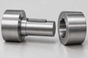

With a transition fit, a replacement shaft can meet its diameter limits and still assemble differently from the shaft it replaces. The permitted hole and shaft sizes overlap, so one pair may have clearance while another has interference. That difference can follow from the drawing itself.
Before ordering the parts, check whether the connection can accept both outcomes. A requirement for easy removal, a fixed assembly force, or frictional retention needs more than the words “transition fit.” The useful starting point is the full size relationship between the two mating features.
One Drawing, Two Conforming Pairs
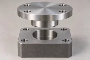
Consider a cylindrical locating pin and its mating bore. The following limits are invented to demonstrate the calculation. They are not ISO fit-table values or a recommended tolerance:
- Bore diameter: 20.000–20.020 mm.
- Pin diameter: 20.005–20.015 mm.
Define C as the bore diameter minus the pin diameter. A positive C gives diametral clearance; a negative C gives diametral interference. These are diameter differences, not radial gaps.
The two extreme combinations are:
C_min = smallest bore − largest pin = 20.000 − 20.015 = −0.015 mm.
C_max = largest bore − smallest pin = 20.020 − 20.005 = +0.015 mm.
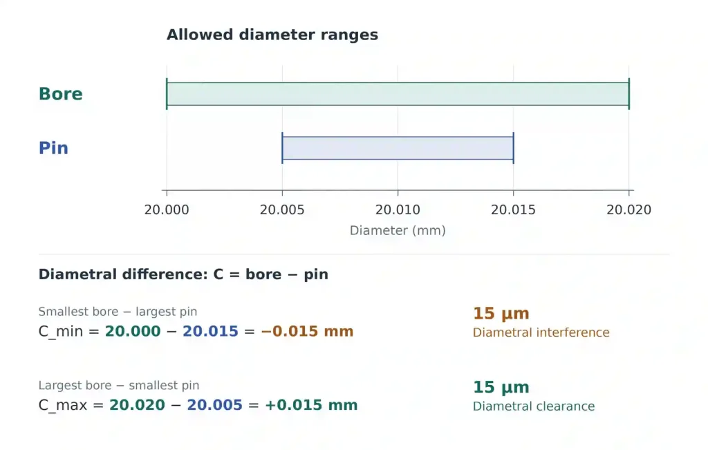
The permitted range therefore crosses zero: up to 15 μm of diametral interference or 15 μm of diametral clearance. Two pairs inside those same limits illustrate the practical difference:
| Illustrative pair | Bore diameter | Pin diameter | Bore minus pin | Size relationship |
|---|---|---|---|---|
| A | 20.018 mm | 20.006 mm | +0.012 mm | 12 μm diametral clearance |
| B | 20.003 mm | 20.014 mm | −0.011 mm | 11 μm diametral interference |
Neither pair violates the stated diameter limits. Rejecting pair B solely because it does not slide in like pair A would introduce an assembly requirement that these size limits do not guarantee.
This calculation assumes that the sizes describe the same specified finished condition at the agreed reference temperature. Shape, surface condition and alignment still affect actual assembly. A positive diameter difference alone does not prove that a long or misaligned pair will slide freely, and the interference value alone does not give the required insertion force.
An ISO fit designation packages the size requirements more compactly, but it still needs both mating features and the nominal size. In a hole-basis system, H means the hole’s lower deviation is zero; it does not mean every hole is exactly nominal. The tolerance grade and nominal-size range determine the applicable tolerance width. H7 by itself specifies a hole tolerance class, not the complete shaft-and-hole fit.
Schaeffler’s Technical Pocket Guide explains the fit categories, tolerance classes and extreme size combinations. Read the actual upper and lower limits for the chosen nominal size before deciding what a fit designation permits.
Decide Whether Both Outcomes Are Acceptable
The arithmetic identifies the range to assess. The connection’s function determines whether that range is suitable.
For removal without pressing, the interference end needs attention. If every replacement pin must slide out during routine maintenance, a transition fit does not provide that guarantee. Review a clearance requirement with enough allowance for the actual geometry, surfaces and service conditions. Calling the fit “removable” does not resolve an allowed interference condition.
For retention by friction, the clearance end needs attention. A pair with clearance cannot provide the interference-generated contact pressure assumed in a press-fit design. If the joint relies on that pressure to resist axial movement or transmit torque, review an interference-fit design and its load capacity. The press fit tolerance guide covers the material, wall, surface and assembly issues that belong to that route.
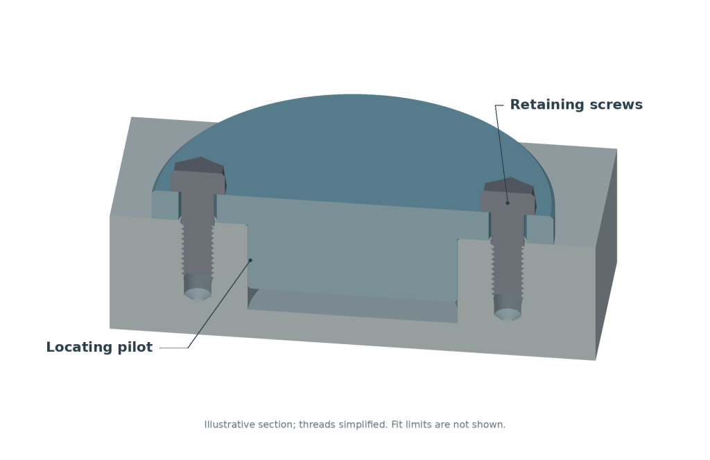
For location with a separate retaining feature, both outcomes may be usable. A cylindrical pilot may locate a cover while screws retain it axially. The designer still needs to accept the possible clearance-related movement and the assembly or removal effort at the interference end. Diameter fit also does not establish the pilot’s position relative to the bolt pattern or other functional features.
Tightening both tolerances does not necessarily remove this choice. For another illustrative calculation, narrow the bore to 20.008–20.012 mm and the pin to 20.009–20.011 mm. The range of C becomes −0.003 to +0.003 mm. Variation is smaller, but both clearance and interference remain possible. To exclude one outcome, the relationship between the limits must change; narrower tolerances alone may add machining cost without meeting that objective.
Put the selected limits on the relevant component drawings and make their inspection stage clear. If a mating feature will be plated or otherwise changed after machining, its pre-finish size is not automatically the size to use in the final fit calculation. For a CNC turning enquiry, include the mating bore’s finished limits with the pin drawing, or the mating shaft’s limits with the sleeve drawing. State any required assembly or removal test separately from the diameter limits.
A New Batch Can Change the Assembly Mix
Suppose the first delivery contains bores near the upper end of their permitted range and pins near the lower end. Many pairings may have clearance. A later delivery can move toward smaller bores and larger pins while remaining within exactly the same drawing limits. More pairings may then have interference.
The tolerance bands do not tell you how frequently either result will occur. Even the symmetric −0.015 to +0.015 mm range above does not establish a 50/50 split. That would require information about the actual bore and pin size distributions and how the parts are paired. A successful first assembly does not establish the behavior of the remaining stock or a future delivery.
When a repeat order feels tighter, retain the component measurements and identify which pin went into which bore. Compare the signed diameter differences before concluding that the supplier made an out-of-tolerance part. If the size relationships do not explain the change, check the relevant form, surface, burr, temperature and alignment conditions. Avoid polishing or sorting the components first and losing the evidence of the original condition.
Selective pairing can change the delivered assembly mix, but it creates a different supply arrangement that needs agreement and control of the paired parts. It should not silently replace a requirement for unrestricted replacement from stock.
If every permitted pairing must meet the same assembly requirement, assess both limits of the fit against that requirement. When one end is unacceptable, revise the fit or the connection design. A repeat order should not depend on the next batch happening to fall on the more convenient side of the tolerance bands.