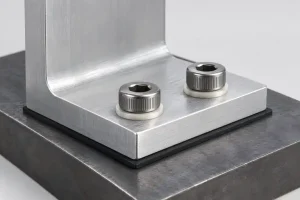

An insulating washer under a bolt head can leave a steel–aluminum joint electrically connected. The bolt shank may touch the aluminum hole, the mounting faces may still meet, or a separate wire may connect the parts. A visible plastic barrier does not prove that the assembled metals are isolated.
Galvanic corrosion requires an electrical connection between materials with different corrosion potentials in the environment, plus a conductive electrolyte linking their exposed surfaces. Aluminum coupled to carbon steel or passive stainless steel can suffer accelerated attack in a suitable wet environment. Control therefore depends on the complete connection and its exposure, not simply on ordering a corrosion-resistant fastener.
For a machined bracket, the purchasing decision is whether the proposed protection works with the fastening arrangement, load and electrical requirements. Define that arrangement before comparing coated parts, isolation kits or assembled units.
Trace Every Metal Contact in the Fastening Stack
Consider an illustrative aluminum bracket attached to a steel support. A steel bolt passes through the bracket and threads into the support. The drawing adds an insulating washer beneath the bolt head. Assume the bolt remains electrically connected to the support through its threads.
Start at the bracket and trace every route to the support. The head contact is only one route. Contact between the bolt shank and the hole wall would connect the bracket to the same steel support, even if the head washer performs as intended. Direct contact beneath the bracket would bypass both the washer and any sleeve around the bolt.
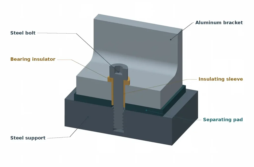
Use the assembly section to record what actually separates each interface:
| Possible contact in this joint | What must be resolved for electrical isolation |
|---|---|
| Bolt head or metal load-spreading washer against the bracket | An approved insulating bearing element must separate the conductive hardware from the aluminum without being bridged at its edge. |
| Bolt shank against the aluminum hole wall | Identify how shank-to-hole contact is prevented. If a sleeve or shoulder bushing is used, define its coverage and keep it intact during installation. |
| Bracket underside against the steel support | The separating layer must cover the intended interface; an exposed edge or locating feature must not recreate metal contact. |
| Dowel, second fastener or another attached metal component | Include each additional connection in the same path review. Isolating the illustrated bolt does not isolate the whole assembly. |
This is an electrical-path review, not a validated fastening design. The components in the table still need suitable strength, dimensions and environmental resistance.
ASSDA’s galvanic-corrosion guidance explains that electrical contact can occur through a bolt, wire or other external connection. It also cautions against relying on paint as electrical insulation at locations where assembly or movement can damage it.
The drawing must show the separation, not merely name an insulating washer. A supplier should be able to identify which component interrupts each unintended conductive route.
Decide Whether the Joint Must Remain Electrically Connected
Some assemblies require electrical bonding: an intentional conductive connection for a function such as grounding or shielding. That requirement changes the protection strategy. A request to isolate the aluminum completely may conflict with the equipment’s electrical design.
Suppose the bracket and support receive a separating pad, a bolt sleeve and insulating washers, but a bonding strap connects them elsewhere. The strap restores an electrical path between the two metals. The local barriers may still protect contact surfaces, but the corrosion assessment must treat the parts as electrically connected wherever a common electrolyte can reach their exposed surfaces.
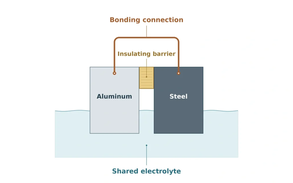
Moving the connection to a separate bonding point does not, by itself, remove galvanic coupling. Keep any required protective bond and have the design address corrosion around the intended conductive arrangement. Do not let a supplier omit the bond to achieve an isolation result.
This distinction also changes acceptance. An isolation check and a bonding-continuity check ask different questions. Define the intended circuit, test points, assembly state and acceptance method before ordering. A continuity reading through an installed bonding strap does not prove that the local sleeve has failed; conversely, checking loose insulating parts says little about the completed assembly.
Record whether the bracket must be electrically isolated or deliberately bonded. “Prevent galvanic corrosion” alone leaves that decision unresolved.
Review the Wet Surfaces and Coating Damage
The electrical path is only part of the problem. Identify where rain, condensation, washdown liquid or salt-contaminated moisture can create a conductive film. A dry-looking outer face can coexist with moisture retained under the bracket. Review the installed orientation, joint edges and any enclosed recesses where liquid can remain.
Sealing and drainage need a consistent arrangement. Show which interfaces are sealed and where incidental water can leave. Adding a sealant bead without considering entry points and trapped pockets can leave the underlying exposure unresolved. Electrical isolation also does not eliminate corrosion mechanisms that can attack a metal independently.
Specify the actual steel surface. Bare carbon steel, passive stainless steel and zinc-coated steel are different corrosion partners. A stainless fastener’s resistance to rust does not establish protection of adjacent aluminum. Zinc is a metallic protective coating, not an insulating layer; its condition and eventual loss affect which surface is exposed. The aluminum versus stainless steel comparison covers the broader material-selection trade-offs.
The exposed areas matter as well. A small anodic aluminum area coupled to a larger wetted cathodic area can face concentrated attack. Consider a local defect in an aluminum coating while a connected steel surface remains exposed to the same electrolyte. The relevant area is the wetted, participating surface, not the total mass or outline of either part. This is a reason to review coating coverage and damage together, not a reason to leave aluminum unprotected.
Keep holes, edges and assembly damage in the finish specification. Define any masking and permitted repair. An approved coating on a flat sample does not show that the same protection remains intact after a washer is tightened against the actual bracket.
Make the Protected Joint Part of the Order
Isolation components change the mechanical stack. A sleeve needs room inside the hole; a flanged bushing or washer changes the bearing arrangement; a separating pad changes the bracket’s installed height. These changes can affect locating features, bolt length and available thread engagement. Show them in the assembly drawing before releasing the individual CNC drawings.
The insulating material must also withstand its assigned load. A polymer layer that creeps or relaxes under sustained compression can reduce clamp force. Review the material’s behavior at the relevant temperature and exposure rather than substituting an arbitrary plastic washer. If a metal compression limiter is proposed, trace its contacts too: it may solve a load problem while creating another conductive route.
Define which faces carry the clamp load and how the sleeve length fits that arrangement. Check hole-edge burrs, washer support and the assembly procedure for damage to the barriers. Tightening requirements belong to the approved joint, including its coatings and lubrication; they should not be carried over unquestioningly after the stack changes.
The quotation must distinguish finished individual parts from a protected assembly. State who supplies and installs the sleeve, bearing insulator, separating pad and sealant, and who restores protection after fitting or rework. If the buyer performs final assembly, the supplier’s inspection of the separate parts cannot confirm the final electrical path.
Where assembly verification is required, agree on a representative configuration using the intended hardware, finishes and installation method. Check the specified isolation or bonding condition after assembly, along with the mechanical requirements. A result on one dry assembly does not establish long-term corrosion performance; any exposure testing needs its own agreed conditions and acceptance criteria.
For a CNC machining review, include a section through the fastening stack, identify the required conductive connections and mark the surfaces that may become wet. Those details let the hole geometry, finish coverage and isolation-component seats be reviewed together. A quote that supplies only the machined bracket should make the remaining assembly protection explicit.