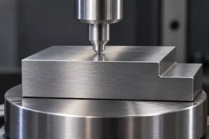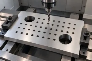

Rockwell, Brinell and Vickers hardness tests leave an indentation. On a finished machined part, that mark may be unacceptable on a seal track, bearing journal or thin edge. The test location therefore needs to be planned alongside the material and heat-treatment requirement.
For metal hardness testing, the first practical question is whether the specified method can be used at a permitted location on the part. If it cannot, the order needs an agreed alternative: another location, a different test method, or a separate specimen. Those choices can change the evidence obtained and the number of parts available for delivery.
Choose a Place for the Indentation
A hardness requirement and a usable test site are separate decisions. A drawing may specify Rockwell C hardness, yet leave no accessible surface where the part can be supported and an indent is allowed. Discovering that conflict after finish grinding leaves the supplier choosing between damaging a functional surface and testing somewhere the buyer did not intend.
Mark the proposed test area before machining starts. Identify what the reading is meant to assess: the material at a working surface, a particular heat-treated region, or another defined location. A convenient end face may be physically easy to test but outside the region that matters to the application.
The measurement also depends on how the test is made. Rockwell determines hardness from the change in penetration depth during a defined loading sequence. Brinell and Vickers use measurements of the residual indentation. The method, scale and applicable force must suit the material and specimen geometry; choosing a smaller impression is not enough by itself.
The NIST guide to Rockwell hardness measurement explains why specimen support, thickness, surface preparation and curvature affect the result. Use the applicable test standard and agreed procedure to select the actual conditions rather than treating every flat-looking patch as suitable.
| Proposed test site | What needs checking | Arrangement to agree before machining |
|---|---|---|
| A round bearing journal | The indent may damage the running surface. Curvature affects the test, and the part must remain stable under load. | Identify a permitted test region and a suitable setup. Any applicable curvature correction must be valid for the selected method and geometry; grinding a flat changes the part. |
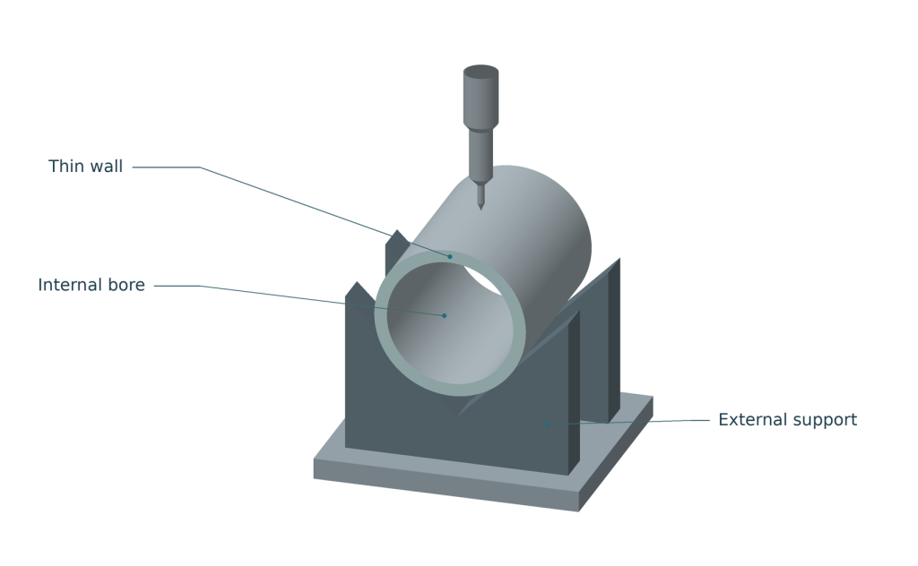
| A thin wall above an internal bore | The wall may flex or be too thin for the selected test, even when the part is held firmly. | Check the wall and support against the method’s requirements. If direct testing is unsuitable, agree another method, location or specimen and the acceptance basis for it. |
| A narrow machined land | The impression may be too close to an edge or another indent. Tooling may also obstruct the indenter or optical measurement. | Reserve an accessible area with the required spacing, or select a suitable specimen route. A smaller indent still needs valid test conditions. |
Clamping the part securely does not make a thin wall suitable for every hardness test. The material beneath the indentation and the way the test force is supported both matter. Stacking separate thin pieces is not a substitute for adequate specimen thickness.
Surface preparation belongs in this plan. Remove only what the approved procedure permits, using preparation that avoids changing the tested material through heating or cold work. Grinding away a shallow hardened layer to obtain a smooth test surface can remove the very region being assessed.
For coated parts, specify whether the requirement concerns the substrate, the coating, or a defined coated condition. Record the test stage accordingly. An unplanned indent through a coating or an unapproved ground patch can leave both the measurement and the delivered surface in dispute.
When the Part Needs a Separate Test Specimen
If no acceptable direct test location exists, allow for the specimen before production quantities and finishing operations are fixed. A dedicated test piece might be a section cut from an additional production part, or a separately prepared coupon whose suitability has been agreed. These routes have different consequences for cost, traceability and what the result represents.
Sectioning an actual part lets the test reach material that the external surfaces conceal. It also consumes that part and requires careful cutting, mounting and preparation. Identify the section and test locations on a sketch so the laboratory examines the intended region rather than whichever face is easiest to polish.
An extra coupon can preserve the delivery quantity, but it needs a reason to represent the specified condition. Material identity alone is insufficient: the heat-treatment history and relevant geometry also need consideration. The alloy steel versus carbon steel guide explains why the section present during hardening matters when comparing surface and internal properties.
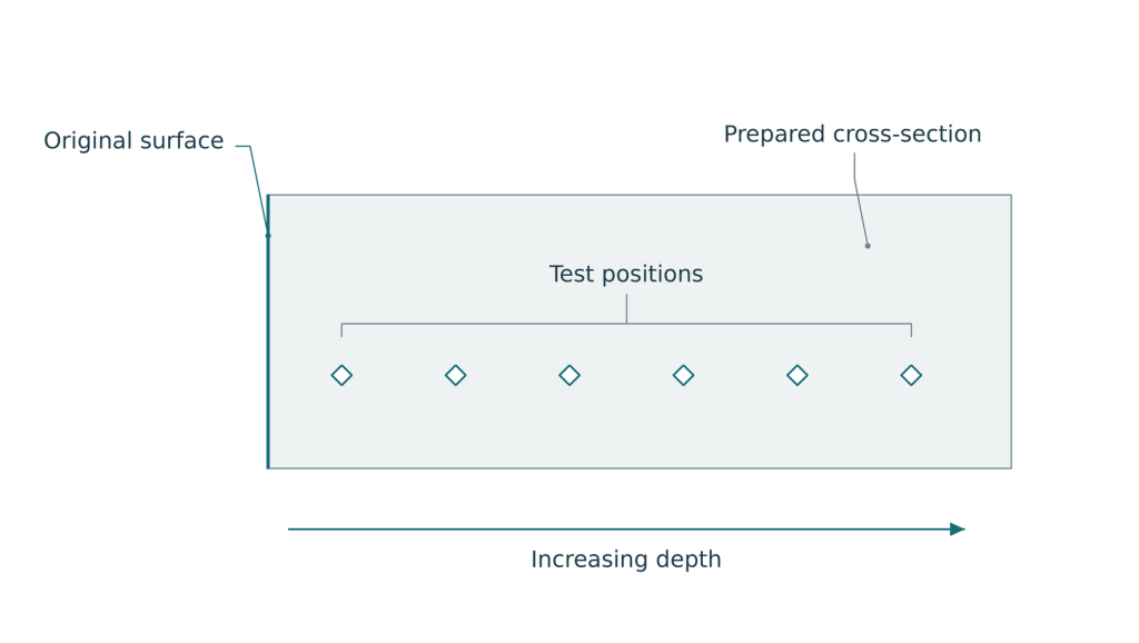
A hardness-depth profile is one reason to prepare a section. As described in Struers’ Vickers testing guidance, a series of indentations from the surface inward can show how hardness changes with depth. The applicable hardening process and specification determine how any case-depth requirement is evaluated; a single surface reading cannot supply that profile.
Keep the specimen linked to its source part or batch, processing condition and test location. If testing occurs before a later operation that could change the required condition, the acceptance plan must address that later operation too.
When arranging CNC machining services, identify any additional part needed for sectioning separately from the finished delivery quantity. Agree who prepares and tests it, and whether the remaining section will be retained for a possible repeat examination. This puts specimen preparation into the quotation while the production route can still accommodate it.
When the Supplier and Incoming Results Disagree
Start by checking whether the two results describe comparable tests. A direct Rockwell result and a value converted from Vickers are different records, even if both are displayed as HRC. Hardness conversions are approximate and limited by the materials and conditions behind the conversion. Preserve the original measured result and identify any conversion; use an agreed acceptance basis before substituting it for the specified test.
Then place the two test locations on the same part sketch. One reading may come from a permitted end face and the other from a curved working surface. They may also represent different manufacturing stages, such as before and after grinding. Comparing the numbers without those details can turn a location or preparation difference into an apparent material failure.
If the locations and conditions are comparable, review the setups: surface preparation, specimen stability, thickness, indent spacing and the testing machine’s verification records. For optically measured impressions, include the preparation and measurement conditions. Investigate these causes without assuming that either the supplier or receiving inspection must be wrong.
A repeat measurement needs a valid new position with the required spacing. Retain the original readings alongside the repeat results and the reason for retesting. Repeating measurements until one passes conceals the disagreement instead of resolving it.
The acceptance plan should name the procedure and specimen used to resolve a disputed result. Agree whether a further test on the part is permitted, whether a retained section is available, or whether another part must be sacrificed. Make that decision before an incoming inspector alters the only available evidence.