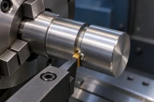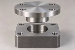

The round hole prepared before broaching can remain part of the finished internal profile. In a hexagonal socket, an oversized pre-hole may leave curved reliefs between the surviving flat portions. A buyer expecting six uninterrupted flats needs that difference resolved before accepting the process.
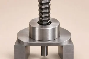
Broaching removes material with cutting edges arranged to produce a required form. Internal applications include keyways, splines, squares and hexagons. A long, progressive-tooth broach, a rotary broach and a single-point CNC broaching tool use different cutting motions. They do not require the same access or part preparation.
For a machined component, specify the profile that must remain, then ask which broaching method can produce it in the stated material condition and quantity.
A Round Pre-Hole Can Remain in the Finished Polygon
An internal broach starts from an opening. The prepared hole affects both how much material the tool must remove and which surfaces can exist afterward.
For a hexagon, distinguish the distance across opposite flats from the larger distance across opposite corners. A circular pre-hole can extend beyond the nominal flat surfaces while still leaving material to be cut at the corners. The finished opening then contains straight flat portions interrupted by arcs from the original hole.
Consider an ideal, concentric example:
- Nominal hexagon size across flats: 8.00 mm.
- Prepared round hole: Ø8.10 mm.
- Distance from the axis to a nominal flat: 4.00 mm.
- Prepared-hole radius: 4.05 mm.
At the midpoint of each nominal flat, the pre-hole has already removed material 0.05 mm beyond that flat. Broaching the corners cannot restore material already removed by the pre-hole. Under the stated geometry, a curved relief remains in each of the six flats.
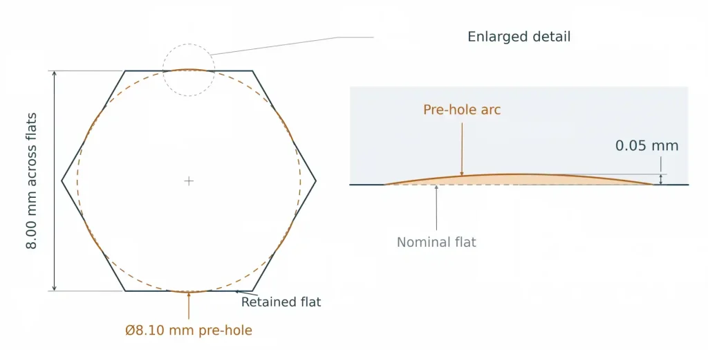
These dimensions illustrate the geometry only. They are not a recommended pre-hole size, machining allowance or tolerance. Hole-size variation and misalignment can change the extent and symmetry of the reliefs.
If uninterrupted flats are required, make that requirement explicit and have the supplier select compatible preparation and tooling. If reliefs are permitted, define their allowable extent instead of approving any opening that accepts a mating hexagon. Acceptance depends on the required contact, clearance and load transfer; insertion alone does not establish those properties.
The same distinction appears in square-hole tooling: a tool intended for a relieved profile is not automatically interchangeable with one intended to produce a full square. For an internal spline, specify the complete spline form and fit requirements rather than treating tooth count and one diameter as a complete definition.
Choose the Cutting Motion for the Available Space
A through-opening may suit a progressive-tooth push or pull broach. Successive cutting teeth remove increments of material as the tool travels through the workpiece. The setup must accommodate the tool, its guiding arrangement, the cutting load and travel beyond the part.
Rotary broaching uses an angled broach in a suitable holder to engage the form progressively around its perimeter. It can produce suitable polygonal sockets in blind holes without pulling a long tool through the opposite side. That does not make every blind profile suitable: form size, depth, material, holder clearance and chip space still need review.
Single-point CNC broaching uses repeated cutting strokes, with controlled infeed between strokes. It can provide another route for selected internal features, including suitable blind features. The tool still needs a workable cutting stroke, return motion and chip-removal arrangement.
| Proposed route | Space the part and setup must provide | What the buyer should confirm |
|---|---|---|
| Progressive-tooth through broaching | A starting opening, guiding access and enough travel for the required teeth to pass through | Whether the selected tool produces the specified full or relieved profile, and whether the fixture leaves its exit clear |
| Rotary broaching | A prepared entry, suitable holder access and space beyond the required form in a blind hole | Permitted pre-hole remnants, lead chamfer, usable form depth and chip clearance |
| Single-point CNC broaching | Access for the cutting edge, repeated strokes and a return path | Any proposed end relief, the surfaces it changes and how chips will leave the cut |
“Broached in one pass” describes a particular tool and operation. It is not a definition that applies to every broaching route. Some push-broach arrangements use multiple passes, while single-point methods build the feature through repeated strokes.
Where the feature is a parallel-key connection, the separate keyway machining review covers the fit between the shaft, key and hub. Choosing a cutting motion does not replace that assembly review.
Specify the Length That Must Engage
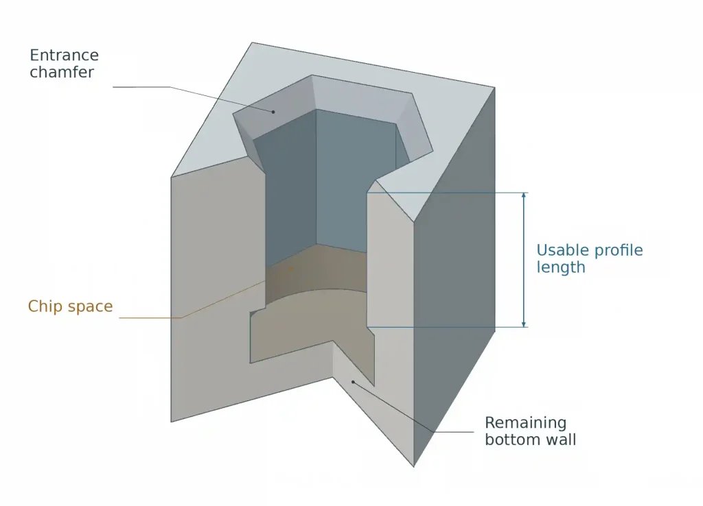
A blind socket needs an axial section as well as a front view. Mark the length over which the required profile must be usable, the entrance chamfer and the permitted geometry beyond the working portion.
For internal rotary broaching, the prepared hole needs room beyond the broached form for chips. A suitable bottom recess may help chip breakaway, and the process may include a separate chip-removal operation. Slater Tools’ part-preparation guidance distinguishes pre-hole diameter, pre-hole depth and lead chamfer. Its recommendations describe its tooling; they should not be copied onto every part as universal dimensions.
The entrance chamfer is also part of the length calculation. A mating hexagon may enter that chamfer before its full working faces engage. At the other end, extra drilled depth provides clearance but does not necessarily provide more usable polygonal form.
Specify the required profile length from a defined face or other drawing reference. Then show where any incomplete form, chip space or relief is allowed. A supplier proposing a deeper hole or a larger recess should also check the remaining wall and nearby features. The blind-hole depth guide explains the difference between usable cylindrical depth and the deepest drill-point position.
The inspection method must reach the region being accepted. A check across flats near the mouth cannot establish the full profile farther down. A form plug can provide useful evidence when its dimensions, lead, insertion depth and acceptance rules match the drawing. However, a GO plug entering the socket does not by itself prove that the flats are uninterrupted or that the pre-hole reliefs meet their limits. Include a suitable profile check when those requirements apply. An ordinary mating component does not automatically check every size, shape or location requirement.
Keep orientation separate from profile size. If a hexagon or spline must align with an external flat, cross-hole or another feature, define that relationship. The supplier must account for it in both the machining setup and inspection.
Tool Availability Can Change the Order Economics
Broaching does not have one minimum economical batch size. An available standard tool may make a short run practical. A custom profile may require a new broach, guiding components, fixtures or gauges before the first acceptable part can be delivered.
Ask whether the proposed tool already exists and whether it matches the complete profile. A similar nominal size is insufficient if the tool leaves reliefs that the drawing prohibits, cannot cover the required length or produces the wrong fit.
Compare preparation and completion work alongside the cutting operation. The scope may include making the pre-hole, machining the entry chamfer or end relief, broaching, removing retained chips, deburring and checking the finished profile. A short cutting stroke does not describe the total manufacturing time.
For repeat supply, distinguish the first order from later orders that can reuse suitable tooling. Agree who owns any dedicated tooling, how its condition is maintained and whether a drawing revision would require modification or replacement. A projected repeat quantity should not be treated as a confirmed order.
The material grade and hardness at the broaching stage also belong in the review. If later heat treatment or finishing can change the profile, identify the delivered condition in which dimensional acceptance applies. Existing tooling should be assessed against that complete route.
For a CNC machining review, send the internal profile together with a longitudinal section, the permitted flat reliefs, required engagement length and any orientation requirement. Include the material condition and first-order and repeat quantities separately. RapidEfficient can coordinate review with machining suppliers to compare feasible tooling and preparation routes against the same finished-part requirements.