
A 4 mm-wide groove does not necessarily need a 4 mm-wide insert. It may be formed with one full-width cut or machined with a narrower tool in several positions. Those routes control the groove walls differently and can carry different tooling and machining costs.
Grooving in turning produces a recess in a rotating workpiece. External and internal circumferential grooves are cut mainly by radial feed; a face groove is entered mainly along the spindle axis. Parting off continues the cut to separate the part. A groove leaves the required material connected.
When comparing quotations, establish how the proposed tool and its movements will produce the finished profile. The width written on the drawing is only part of that decision.
A Single Cut Ties the Width to the Insert
On an external circumferential groove, a full-width radial plunge forms both walls with the same cutting edge. Its actual width and corner shape therefore matter directly. A nominally 4 mm insert is not evidence that a finished groove meets a 4 mm width requirement with its specified tolerance.
The supplier needs to match the cutting-edge dimensions and profile to the drawing, then account for the setup and cutting conditions. Moving the entire insert axially shifts both walls together; that adjustment alone cannot independently correct the distance between them.
A narrower insert separates some of that work. One position can establish one wall, and another position can establish the opposite wall. Overlapping cuts remove the material between them, with finishing operations where needed.
For an illustrative rectangular cutting envelope, ignore corner radii and finishing allowance. A 2.50 mm-wide edge used at two axial positions 1.50 mm apart covers:
Total axial width = cutting width + position difference = 2.50 + 1.50 = 4.00 mm.
The two cut envelopes overlap by 1.00 mm. This is a geometry example, not a prescribed roughing or finishing cycle. The width of a real groove still depends on the effective cutting edges, their positions and the finished wall profiles.
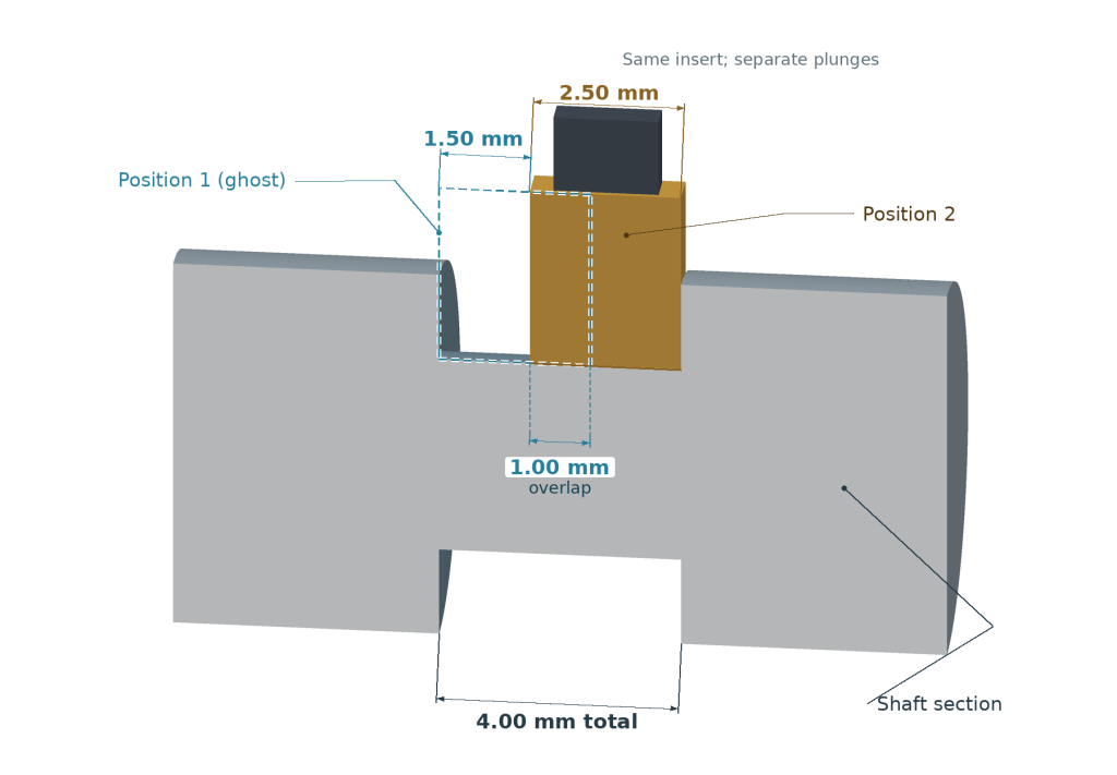
Multiple plunges and side turning are different operations. A tool used for separate radial cuts should not automatically be fed sideways while engaged. A groove-turning route needs an insert and holder suitable for that lateral cutting action.
Read Depth in the Correct Direction
Moving the same groove section from an outside diameter to a bore or an end face changes the tool arrangement. It can also change what a stated dimension means.
The following invented dimensions illustrate the distinction. They are not recommended groove sizes.
| Groove location | Given diameters | What their difference describes | Dimension still needed |
|---|---|---|---|
| External circumferential groove | Adjacent outside diameter 40 mm; groove-root diameter 34 mm | Radial depth = (40 − 34) ÷ 2 = 3 mm | Axial groove width |
| Internal circumferential groove | Bore diameter 20 mm; groove-root diameter 26 mm | Radial depth = (26 − 20) ÷ 2 = 3 mm | Axial groove width and distance from the bore entrance |
| Annular face groove | Outer boundary diameter 40 mm; inner boundary diameter 34 mm | Radial width = (40 − 34) ÷ 2 = 3 mm | Axial groove depth |
For the face groove, the 3 mm result is a width, not a cutting depth. A section through the spindle axis should also show how far the groove extends into the end face.
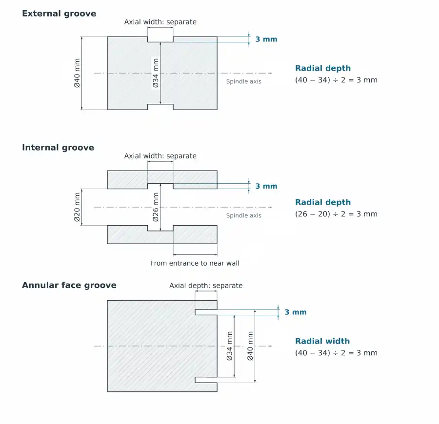
For the internal groove, radial depth and axial reach are separate. A groove farther inside the bore can require more tool overhang even when its width and radial depth stay unchanged.
Tool size creates a trade-off here. With other factors unchanged, reducing the boring-bar diameter leaves more room for chips but reduces stiffness. A narrower cutting edge can reduce cutting load, yet it may add cuts and finishing work. The useful comparison is the complete tool assembly at the required reach, rather than the insert width alone.
Face Grooving Has a First-Cut Diameter Range
An axial face-grooving tool must fit within an annular cut as it advances. The blade behind the cutting edge needs clearance from the circular walls. An ordinary external grooving blade cannot be assumed suitable merely because its insert is narrow enough.
Face-grooving holders are specified for a range of first-cut diameters. Sandvik Coromant’s face-grooving guidance distinguishes this range from cutting depth and insert width, and also identifies the tool curve and handedness needed for the setup.
Use that distinction when reviewing a proposal. A tool may have enough cutting width and projection but an unsuitable body shape for the planned entry diameter. Another tool may suit the diameter but lack the required axial cutting depth.
The first-cut range is not automatically a limit on every diameter in the finished, widened groove. Subsequent cuts can remove material beside the initial channel, provided the tool and proposed movements remain suitable. Ask which diameter is used for the first entry and how the remaining groove is opened and finished.
A change to the face-groove diameter can therefore affect tooling even when its width and depth stay the same. Confirm the exact holder and route before accepting a quote based only on an available insert size.
Compare Routes Against the Same Finished Groove
For a repeat run, a dedicated form insert may be worth considering if it replaces several operations. For a small order, suitable existing tooling may avoid that initial expense. The comparison needs the actual order quantity and machining plan; fewer cuts do not automatically mean a lower delivered part cost.
Check where each proposal finishes the two walls, the bottom and the corner transitions. A route based on several plunges may still need a separate pass to meet the required bottom profile or surface texture. That work belongs in the quoted route, rather than being treated as an unexpected correction after the first part.
Changing the groove to suit a stocked tool is a separate design decision. For a retaining-ring groove, the selected ring’s requirements constrain the width, diameter and corner details. For a sealing groove, use the O-ring groove design guide to review the gland and mating geometry. A convenient cutting width does not establish either function.
For a CNC turning review, highlight the groove section and identify which width, root size, wall positions and corner limits must remain fixed. Include the order quantity so the supplier can compare a form insert with a route using narrower tooling. For an internal or face groove, keep the entrance, nearby shoulders and full groove location visible in the model.
Two suppliers can use different cutting routes and still deliver the same specified groove. The comparison changes when one quote assumes a wider slot, a larger corner radius or an unfinished surface that the drawing does not permit.