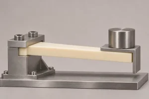

A machined plastic support may keep a fixture clear of its base when first loaded, then allow the gap to close during a long hold. After unloading, the gap may open again. Measuring only at that last stage misses the condition that stopped the assembly working.
Plastic creep is time-dependent deformation under sustained stress. For a purchased part, the useful question is how much movement the assembly can accept while the load remains applied. A dimensional report taken before loading cannot answer that question by itself.
Keep the initial loaded position, movement during the hold, and recovery after unloading separate. These observations support different conclusions about whether a proposed material and machined geometry are suitable.
Measure the Working Gap Under Load
Consider an illustrative plastic support carrying a metal fixture above a fixed base. The critical requirement is the clearance between the fixture and the base at a marked location. The free-state thickness of the support is a different measurement.
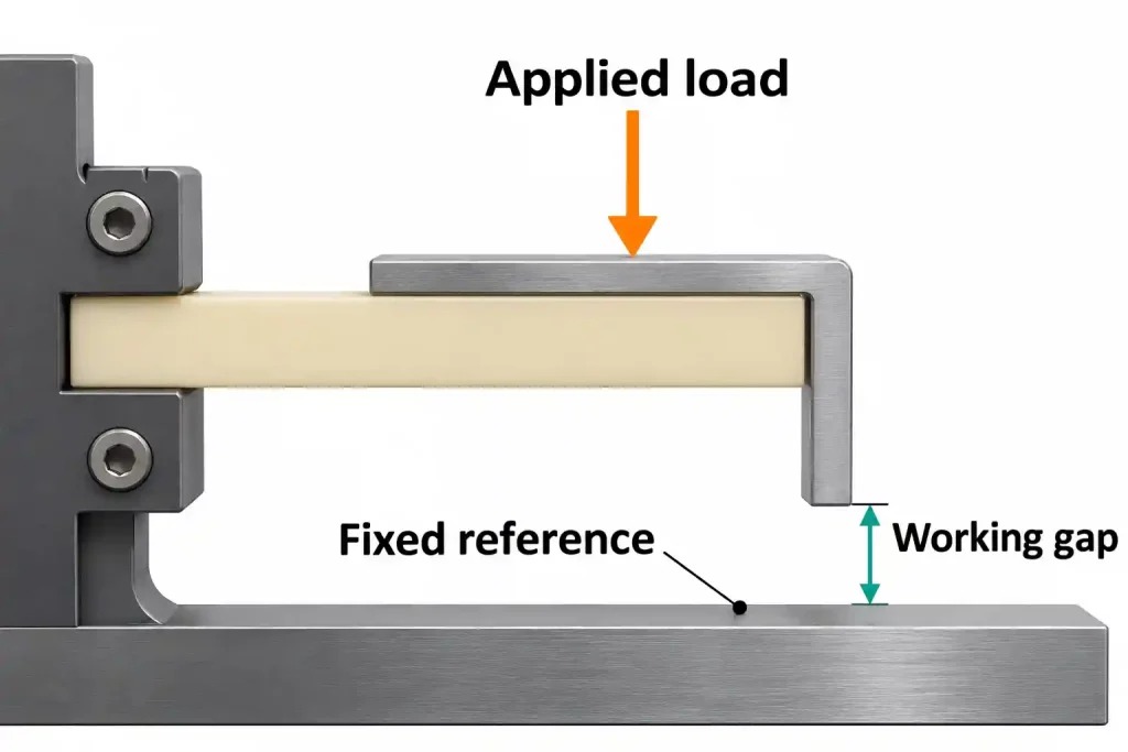
Record the starting geometry before loading, then apply the specified load and record the first loaded reading at a defined elapsed time. Keep the load location, support contacts, measuring point and reference fixed. Loading takes time, so an undefined “initial” reading makes comparisons between trials less useful.
Suppose the first loaded gap is 0.30 mm and the required minimum is 0.20 mm. Under those same conditions, the additional closure allowance is:
Additional closure allowance = 0.30 − 0.20 = 0.10 mm.
These are illustrative dimensions, not material data. The initial loading movement has already been included in the 0.30 mm reading. A prediction measured from the unloaded position must include that movement too. Any further allowance needed for temperature changes, mating-part variation or measurement uncertainty must also fit within the available margin.
Measure the functional gap directly where practical. A displacement reading at another point on a flexible support may not equal the gap change. Likewise, movement of the test frame, seating of contact surfaces or slipping of a clamp can appear in an assembly reading. The gap can fail its functional requirement even before the cause of the movement has been isolated.
Use one record that follows the same specimen through the test:
| Observation point | Load state and measurement | What the reading establishes |
|---|---|---|
| Before loading | Record the conditioned, unloaded geometry and reference points. | The starting state; it does not establish loaded clearance. |
| First loaded reading | Record the applied load, working gap and reading time measured from the start of loading. | The starting loaded position and the margin remaining above the minimum gap. |
| During the hold | Keep the specified load applied; record gap, elapsed time and relevant environmental conditions at planned intervals. | Whether the measured gap remains acceptable during the observed hold. The record alone does not separate material creep from fixture movement. |
| Immediately after unloading | Record the unloaded position and the delay between load removal and measurement. | The first observed recovery state; it cannot replace the final loaded reading. |
| After a defined recovery period | Record the unloaded position, elapsed recovery time and conditions again. | The remaining offset at that time, without proving it is permanent or that the loaded test passed. |
If the requirement applies throughout the hold, choose a recording method and frequency that can detect relevant changes. Two readings taken at the start and end cannot describe an unobserved temperature excursion or temporary interference between them.
ZwickRoell’s overview of plastics creep testing explains strain recording under static load, environmental control and correction for deformation of the test arrangement. The table above is a component-level planning aid, not a substitute for a specified standard test method.
Choose What the Hold Test Must Represent
The hold duration should follow the decision being made. A trial can screen a proposed support, compare two specified versions or verify an agreed operating interval. Those are different claims. A short trial does not establish years of acceptable service simply because no movement was visible.
Before choosing the conditions, examine the material supplier’s time-dependent data. A creep curve may show total strain against time at a stated stress and temperature. A creep-modulus curve expresses stiffness for specified loading conditions and elapsed time. Neither is a single material constant that can replace every short-term modulus value in a drawing review.
Check the named grade, material condition, stress level, temperature, time range and loading mode. For machined parts, also establish whether the data apply to the supplied stock form and orientation. Data from a molded test specimen are not automatically a qualification of an extruded plate or the finished support.
Read the strain reference carefully. If a curve gives total strain from the unloaded state, adding the full initial strain again would count it twice. If it gives only the increase after loading, ignoring the initial movement would understate the total displacement. The same distinction applies to the 0.10 mm allowance in the example: that is additional closure after the first loaded reading, not the total permitted movement from the unloaded position.
Material strain must then be related to the part’s geometry. For a uniformly compressed spacer, shortening relates to strain over its loaded height. A support that bends has a different displacement pattern. A percentage strain on a datasheet is not, by itself, a millimetre value at the fixture’s critical gap.
Temperature and moisture changes can introduce dimensional movement alongside creep. Keep them controlled when isolating creep; reproduce and record the relevant changes when evaluating an actual service cycle. A hotter, shorter trial needs a justified relationship to the intended conditions before it can support a longer-life claim. Cooling the part before measurement introduces another change in state.
Also check whether the assembly controls force or displacement. Holding a plastic element at a fixed deformation can cause its reaction force to fall over time; this is stress relaxation. A bolted joint may change both force and displacement as its members deform. If retained clamping force is the functional requirement, a gap record alone is insufficient. The broader material-selection implications are covered in the Delrin versus UHMW comparison.
Keep Recovery Separate from the Loaded Result
Take the last loaded reading before releasing the force. Then record unloading and recovery as separate events, with their own times. Removing the part, carrying it to an inspection room and waiting for measurement creates an interval during which recovery may already occur.
Delrin’s creep and stress-relaxation guide describes immediate recovery followed by slower recovery after unloading. The amount of movement left after one waiting period should therefore not automatically be labelled permanent deformation.
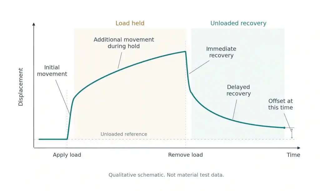
For the illustrative support, a gap that dropped below 0.20 mm during the required hold has failed that clearance requirement. A later unloaded measurement cannot reverse the result. Recovery is still useful evidence: it helps describe the response and plan the next investigation, provided the loaded record is retained.
If the first loaded reading was already unacceptable, investigate the initial geometry, stiffness and support arrangement before blaming long-term creep. If the gap crossed the limit during the hold, investigate the time-dependent movement and the test setup. If the gap stayed acceptable for the agreed trial, report that duration and those conditions; do not extend the conclusion beyond the evidence.
Repeated loading introduces another question. A single hold followed by recovery does not show how the part will respond to repeated service cycles. Reusing the same specimen also carries its earlier load history into the next trial. Record that history or use a defined fresh-specimen comparison.
For a CNC machining review, mark the working gap on the assembly and identify the load and hold conditions used to judge it. Agree who supplies the material data, who runs any component trial, and what evidence is included in the order. A dimensional inspection of the unloaded machined part and a recorded hold test answer different questions; the purchase scope should make clear which is required.