
A spring finger in a CNC assembly must deliver the required contact force over its working travel and recover when released. Choosing spring steel material starts with that force–travel requirement. Geometry and elastic modulus determine the initial stiffness; the material’s strength and condition help determine how much movement it can tolerate before taking a permanent set.
“Spring steel” covers several steel families and supplied conditions. A thin strip attached to a machined carrier and a flexible finger machined into a solid component may need different stock and manufacturing routes. This article follows a flat spring finger, where that choice directly affects the part being purchased.
Set the Force and Travel Together
For a spring that works within its elastic range, stiffness describes the force needed for a given displacement. Hardness measures resistance to indentation. Raising the specified hardness does not provide a matching increase in spring stiffness.
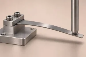
A simple cantilever model makes the distinction useful. Assume a straight, slender finger with a uniform rectangular section, a rigidly fixed root and a transverse point load at its free end. The deflection is small, and the material remains linearly elastic. Holes, local root details and contact movement are excluded.
For this model:
F = E × b × t³ × δ ÷ (4 × L³)
σ_nom = 6 × F × L ÷ (b × t²)
Here, F is the tip force, E is elastic modulus, b is width, t is thickness in the bending direction, and δ is tip travel from the unloaded position. L runs from the fixed root to the load point. σ_nom is the nominal maximum bending stress at the root. These relations follow the rectangular-section cantilever equations in MIT’s beam-bending notes.
Consider three hypothetical fingers with b = 10 mm, δ = 1.0 mm and an assumed E = 200,000 N/mm². The modulus is an illustrative input, not a certified property of every spring steel.
| Finger geometry | Length L | Thickness t | Force at 1.0 mm travel | Nominal root stress |
|---|---|---|---|---|
| Starting geometry | 40 mm | 1.0 mm | 7.81 N | 187.5 MPa |
| Thicker finger | 40 mm | 1.2 mm | 13.50 N | 225.0 MPa |
| Longer finger | 50 mm | 1.0 mm | 4.00 N | 120.0 MPa |
At the same imposed travel, the thicker finger produces more force and higher nominal stress. The longer finger produces less force and lower stress. These comparisons hold travel constant; they should not be read as comparisons under the same applied force.
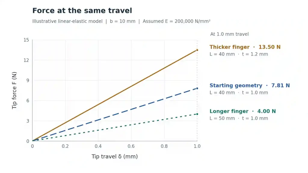
Thickness therefore belongs in the functional tolerance review. In this model, force varies with thickness cubed and inversely with length cubed. Stock thickness, the effective clamping length and the actual contact position can change the force even when the material grade stays the same.
A stronger supplied condition may permit more elastic movement before unacceptable permanent deformation. It must still satisfy the required force at the working position. Check the actual material data rather than converting hardness directly into an elastic modulus. A 0.2% proof-strength value also allows a defined amount of permanent strain in its test; it is not a zero-set limit or a fatigue acceptance criterion.
The table is a preliminary calculation, not an approved spring design. An actual root radius, mounting hole or flexible clamp changes the local response. Large deflection or sliding contact requires a model suited to those conditions.
Strip and Machined Stock Lead to Different Routes
Once the working range is defined, choose the stock product that can provide the required section and final material condition.
A separate flat finger may be cut from strip whose thickness already controls much of the spring response. For example, Alleima 20C is a hardened and tempered carbon-steel strip product listed against 1095. Its data sheet relates mechanical properties to thickness and provides specific blanking and bending guidance. Those details describe that product, rather than every item sold under a 1095 designation.
A stainless alternative can follow a different strengthening route. Alleima 12R11, listed with ASTM 301, is normally supplied as cold-rolled strip. Its property tables distinguish annealed, cold-rolled, and cold-rolled-and-tempered conditions. Its forming guidance also varies with thickness, strength and rolling direction. A replacement should therefore identify the required product specification and condition, not merely change “carbon steel” to “stainless steel” on the order.
Carbon-steel strip needs a corrosion-protection plan matched to the environment. A stainless spring grade may reduce that need, but the actual chemicals and temperature still govern suitability.
If a permanent bend is needed to make the finger, forming ability becomes part of that choice. A high-strength strip suitable for a nearly flat part may require a larger forming radius. Alternatively, a suitable carbon-steel route may form or machine softer stock before hardening and tempering. That route adds thermal processing and a plan for dimensional movement and surface cleanup. Treatment temperatures and forming limits must come from the actual material and process requirements.
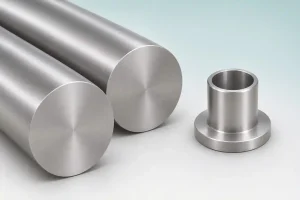
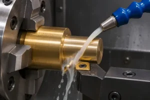
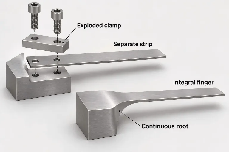
An integral finger creates a different purchase. Its thicker mounting body and thin flexible section must come from compatible stock. Mechanical properties reported for thin rolled strip should not be assigned to a machined bar or plate without supporting product data. For an integral finger, CNC machining connects the root transition, thin section and mounting features in one part. Tool access, support during cutting and any finishing after heat treatment must suit that geometry.
Compare the two constructions at assembly level. A separate strip introduces a joint and a defined clamping length, but allows the carrier and spring to use different materials and makes replacement possible. An integral finger removes that joint, while a damaged spring section can require replacement of the whole component. Include stock availability, forming or heat treatment, edge finishing and assembly work when comparing cost.
For either route, preserve the designed thickness and root shape during finishing. Burr removal, blending and polishing remove material. Specify the intended edge condition where bending stress is high, rather than leaving the supplier to choose an unrestricted edge break. Keep the ordered stock condition and any later treatment traceable to the finished part; the broader CNC material-selection guide explains how supply condition fits into machining planning.
Qualify the Spring at Its Working Positions
A spring finger usually operates between installed positions, not between an unloaded state and one isolated test point. Preload may already bend it before the mechanism begins moving. Record the minimum and maximum operating positions, their forces, and any extra travel during assembly or an occasional overload.
Repeated loading adds a separate requirement. Mean stress, stress range, surface and edge condition, corrosion, and the intended number of cycles affect the fatigue assessment. A spring held deflected for long periods also needs a check for force loss through relaxation at the service temperature.
Published fatigue data need their test conditions attached. The 12R11 data sheet, for example, distinguishes reversed bending with zero mean stress from fluctuating tension and identifies specimen direction and thickness. A preloaded finger cycling in one direction should be assessed against evidence relevant to that loading history. A data-sheet fatigue value is not a promised life for the finished component.
Use representative finished parts in the intended mounting arrangement for functional qualification. The plan should define:
- The force limits at specified working displacements, including the displacement reference and load-contact point.
- The permitted residual displacement after unloading from the agreed travel, with the measurement timing stated.
- The cycle range, environment and acceptance criteria for repeated operation, including any allowed force change or cracking criterion.
Where long holds matter, include a dwell and a force-retention requirement. Agree the test method, sample plan and responsibility separately from routine dimensional inspection.
The results guide the next decision. A finger that recovers but produces too little force calls for a stiffness and geometry review. Residual set calls for investigation of travel, local stress, restraint and material condition. Force loss after cycling or a long hold requires examination of fatigue, relaxation and the mounting arrangement. Choose the material and construction that satisfy the required force–travel range with the agreed durability evidence, then keep that combination under change control.