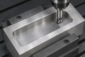

On a drawing, a closed pocket is an empty shape. In a solid blank, that space is still metal. The cutter must open a route into it before it can travel around the walls and finish the floor.
End milling uses the cutting edges around a rotating tool’s periphery and, where the tool design permits, its end. The peripheral edges machine walls; the end edges remove material at the bottom. Entering solid stock adds another demand because the tool must create its own clearance while moving downward.
For a part ordered through CNC milling services, the entry route deserves attention when the pocket has limited entry space, a thin floor or tightly controlled internal corners. This discussion follows a top-accessible pocket with vertical walls. Those features determine which preparation and cutting moves can preserve the drawing.
Match the Entry to the Cutting End
A conventional end mill making a straight axial plunge into solid material needs a center-cutting end geometry. A non-center-cutting tool leaves material beneath its inactive central region, which can interfere with further downward movement. Cutting a side wall successfully says little about that central clearance.
Even with a center-cutting tool, plunge capability depends on the specific tool and application. Cutting speed falls toward zero at the rotational axis, and chips must escape from the confined end contact. Check the manufacturer’s permitted operations and axial cutting data instead of applying side-milling settings to a vertical plunge. Harvey Performance’s tool-entry guide distinguishes straight plunging, ramping and entry through a prepared hole.
A drilled starter hole provides space for the cutter to descend before moving sideways. Its diameter, position and usable depth must suit the actual tool envelope. A hole just described as “deep enough” leaves an important ambiguity: a pointed drill extends below the depth at which the hole reaches full diameter.
For a pocket with a continuous finished floor, put that drill point on the section drawing. If it extends below the permitted floor, subsequent milling cannot fill the depression. A shallower starter hole followed by suitable cutting moves, different hole-making tooling or another entry method may preserve the floor. Any permanent recess beyond the drawing limits needs design approval. The blind-hole depth guide explains the difference between full-diameter depth and drill-tip depth.
Count Tool-Center Travel Inside the Pocket
Ramping lowers the cutter while it moves laterally. A straight ramp consumes length; a helical ramp consumes room for a circular tool-center path. Harvey Performance’s ramping explanation describes those two motions. The usable angle still comes from the selected tool, material and cutting conditions.
Consider an illustrative pocket 50 mm long, 18 mm wide and 8 mm deep. Plan a straight entry along its length using a 10 mm cylindrical cutter. Leave 1 mm of stock on each end wall and 0.5 mm on the floor. Assume the central corridor is unobstructed and the end geometry allows the illustrated motion.
The cutter center must stay one tool radius plus the retained stock away from each end wall:
Available horizontal travel = pocket length − cutter diameter − 2 × end-wall stock
Available horizontal travel = 50 − 10 − 2 × 1 = 38 mm
For a ramp angle α measured from the horizontal plane:
Vertical drop = horizontal tool-center travel × tan α
Using an assumed angle of 3° gives the following geometric budget.
| Quantity | Calculation | Result |
|---|---|---|
| Center-to-wall distance at either end | 10 ÷ 2 + 1 | 6 mm |
| Available straight tool-center travel | 50 − 2 × 6 | 38 mm |
| Drop during that travel at 3° | 38 × tan 3° | About 1.99 mm |
| Intended roughing depth below the top | 8 − 0.5 | 7.5 mm |
| Horizontal travel needed for a 7.5 mm drop at 3° | 7.5 ÷ tan 3° | About 143.1 mm |
One straight traverse therefore reaches only part of the intended roughing depth. Using the full 50 mm drawing length in the ramp calculation would overlook the cutter’s size and the stock reserved at the ends.
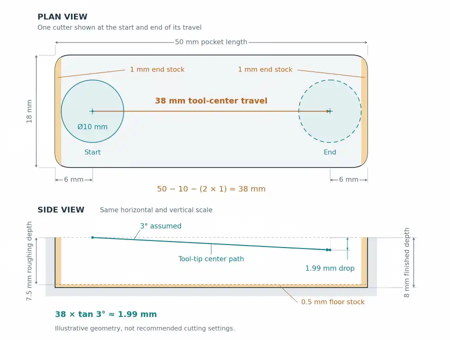
These dimensions and the 3° angle are illustrative inputs, not recommended cutting settings. The calculation checks space, not cutting force, chip removal or cycle time. Actual clearance margins, path transitions and tool restrictions can reduce the usable travel further.
Repeated ramping moves or a suitable helical entry may provide a route to depth. Their direction changes and local engagement need their own toolpath review. Simply steepening the ramp exchanges a space problem for a different cutting condition. Where a helix is proposed, distinguish the swept opening from the smaller tool-center circle and check the tool’s permitted entry-diameter range. The helical milling guide covers that geometry and the associated feed relationship.
A ramp also leaves a sloping or stepped boundary in the remaining stock. Reaching the target Z position at one point must be followed by moves that clear the intended area and produce the required floor.
Give the Wall and Floor Their Own Finishing Moves
After entry, the cutter may open a full-width channel before widening the pocket. In full slotting, material surrounds much more of the cutter’s circumference than during a light side-finishing pass. The load and chip-escape conditions change with that engagement. A parameter set selected for a small radial cut should be reassessed before the same tool enters a full-width slot.
Sandvik Coromant’s slot-milling guidance discusses the cutting forces, chip evacuation and deflection involved, including the value of separating roughing from side finishing in suitable slots.
An undersized roughing tool leaves room to approach each wall separately. The finishing path can then remove controlled stock from the wall rather than using the cutter diameter as the sole means of generating the final width. The remaining stock must also be checked at corners, where a larger roughing cutter can leave more material than it leaves along a straight wall.
Keep two corner radii distinct. In plan view, the cutter’s outside diameter limits the internal wall corner it can enter. In section, the cutter’s end-corner geometry affects the transition between wall and floor. A smaller diameter helps with a tight plan-view corner, but changing diameter does not automatically provide the required floor fillet.
Treat the floor as a separate surface in the finishing plan. End-edge geometry, the path across the remaining stock and any retained floor allowance affect how it is completed. A wall-finishing pass around the perimeter may leave the middle of the floor untouched.
For a pocket that locates an insert, compare the finished wall spacing, corner clearance and seating floor with the mating component. Check the specified depth and relevant surface requirements over their intended regions. A part that enters the pocket but rocks on an unfinished central area has a different problem from one that stops at an internal corner.
The Neck and Holder Must Follow the Tip
At the lowest cutting position, the cutter tip is only one part of the assembly inside or above the pocket. The flutes, relieved neck, shank and holder each occupy space. Check their clearance against the walls, nearby bosses and clamps throughout the entry and finishing paths.
Length of cut and reach serve different purposes. A relieved-neck tool can reach a low cutting zone while keeping its non-cutting neck clear of the wall. That neck cannot remove stock that lies above the flutes. If the plan calls for cutting the entire wall height in one pass, the active cutting length must cover the intended contact.
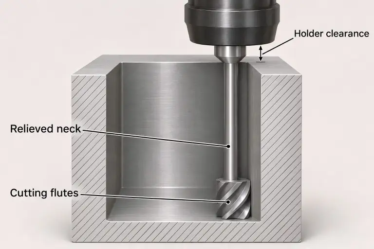
Harvey Performance’s discussion of tool deflection distinguishes long-reach and long-flute tools. Keep projection as short as the access permits while preserving the holder’s required grip. Extending the assembly changes its bending response; extra flute length is not a substitute for checking the complete clearance envelope.
Where interference appears, identify exactly which geometry would have to change. A different tool assembly or a revised path may fit the existing pocket. Widening the opening, enlarging a corner, adding a floor recess or cutting through a side wall changes the part and needs approval if it exceeds the drawing limits.
The practical choice is between a feasible route within the existing envelope and an explicitly approved design change. For the illustrated pocket, first resolve the limited ramp travel and preserve the continuous floor; then verify that the wall-finishing tool and holder can reach their working positions. That sequence keeps a proposed machining convenience from becoming an unapproved feature in the delivered part.