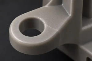

Helical milling uses a rotating milling cutter that travels around a hole while moving along its axis. The combined circular and axial motion creates a helical path, also called helical interpolation or circular ramping. With suitable tooling, it can open a hole from solid material or enlarge an existing opening.
One cutter can serve several hole diameters, but changing the diameter changes more than the programmed radius. It also changes the distance traveled in each orbit, the ramp angle for a given axial pitch, and the relationship between contour feed and tool-center feed. Reusing the same settings without checking those relationships can change the cut substantially.
The useful starting point is the circle traced by the tool center—not the circle shown as the hole diameter on the drawing.
Separate the Hole Circle from the Tool-Center Circle
Consider a cylindrical cutter machining an internal circular wall. In an ideal geometric model, with no allowance or compensation offset:
D_path = D − d
Here, D is the diameter generated by the current pass, d is the effective cutting diameter, and D_path is the diameter of the tool-center orbit.
A 12 mm cutter generating a 20 mm hole therefore follows an 8 mm tool-center circle. Its center is 4 mm from the hole axis. Adding the cutter radius of 6 mm reaches the required hole radius of 10 mm.
These dimensions describe the cutting envelope. They do not establish the actual hole tolerance or prove that the cutter can enter solid material.
If roughing leaves material for a later finishing pass, use the diameter generated during roughing in the calculation. Using the finished drawing diameter for every operation can hide a different orbit at the stage where the tool is most heavily loaded.
The hole diameter, cutter diameter, and tool-center path diameter describe three different things.
Helical movement also does not automatically produce a thread. A normal end mill following a descending circle makes a hole or pocket-entry path. Thread milling requires the appropriate thread-form cutter and motion matched to the thread geometry.
The Same Axial Pitch Makes a Steeper Path in a Smaller Hole
Let p be the axial descent during one complete orbit around the hole. It is not the descent per spindle revolution: the cutter spins many times while its center completes an orbit.
Unrolling the tool-center helix gives a right triangle. Its horizontal length is the orbit circumference, π × (D − d), and its vertical height is p. The geometric ramp angle α, measured relative to the XY plane, is therefore:
α = arctan[p ÷ (π × (D − d))]
For the 12 mm cutter in a 20 mm hole, an illustrative pitch of 0.5 mm per orbit gives:
α = arctan[0.5 ÷ (π × (20 − 12))] ≈ 1.140°
If the hole increases to 22 mm with the same cutter and pitch, the orbit diameter becomes 10 mm and the angle falls to approximately 0.912°. Conversely, reducing the hole diameter makes the same axial descent steeper.
This is a geometric comparison, not a recommended cutting condition. A larger cutter in the same hole also reduces the orbit diameter, so selecting a larger tool does not automatically make ramp entry easier.
Tungaloy’s helical milling guide treats the supported hole-diameter range, axial pitch, and maximum ramping angle as related tool-selection checks. Use the limits for the actual cutter and insert combination. Passing an angle check alone does not approve the pitch, material, reach, or cutting load.
State Which Feed the Program Is Using
The tool center travels a shorter circular distance than the hole contour. For the same time per orbit, their circumferential feed rates have the same ratio as their diameters.
Define F_wall as the intended feed along the circular hole contour in the XY plane, excluding spindle rotation. The corresponding tool-center feed in that plane, F_center,XY, is:
F_center,XY = F_wall × (D − d) ÷ D
This is a circular-path feed conversion. It is not the cutter’s peripheral cutting speed, and it does not select a suitable chip load by itself.
The following example keeps the cutter diameter at 12 mm, pitch at 0.5 mm per orbit, and illustrative contour-feed target at 600 mm/min. It isolates geometry rather than proposing a production program.
| Quantity | 20 mm hole | 22 mm hole |
|---|---|---|
| Cutter diameter, d | 12 mm | 12 mm |
| Tool-center path diameter, D − d | 8 mm | 10 mm |
| Axial pitch per orbit, p | 0.5 mm | 0.5 mm |
| Tool-center ramp angle | 1.140° | 0.912° |
| XY feed ratio, (D − d) / D | 0.4000 | 0.4545 |
| Corresponding tool-center XY feed | 240.00 mm/min | 272.73 mm/min |
Angles are rounded to three decimal places, ratios to four, and feeds to two. Calculations use unrounded values.
For the 20 mm hole, entering 600 mm/min as an uncompensated tool-center XY feed would correspond to a contour feed of 1,500 mm/min in this model. The 240 mm/min result is the converted value, not an amount to subtract from 600.
Changing the hole diameter requires a new feed-basis check, even when the cutter and intended contour feed stay the same.
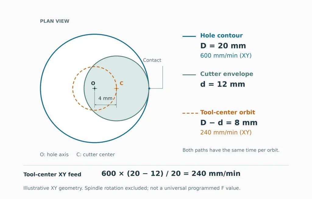
The table deliberately identifies an XY component. During a descending helix, simultaneous Z motion adds to the three-dimensional tool-center path length. Do not treat the table as a universal G-code F value. Confirm whether the control and CAM operation use contour feed, tool-center path feed, or another defined basis.
Also check whether circular-feed compensation is already applied. Applying the ratio again can create an unintended second reduction. Review the posted motion and its feed interpretation, not only the number displayed in the CAM cutting-data field.
Check What the Cutter Leaves at the Center and Bottom
A cutter fitting inside the target diameter does not prove that one descending orbit will clear the entire hole. The swept cutting region must cover the material that needs removal, while the non-cutting portions of the tool remain clear.
A small cutter following a large orbit may leave a central core. A cutter with limited center-cutting capability may instead leave material that interferes with its underside. Sandvik Coromant’s ramping guidance discusses these diameter limits and the remaining material at a blind-hole bottom. Check the selected tool geometry rather than applying one diameter ratio to every cutter.
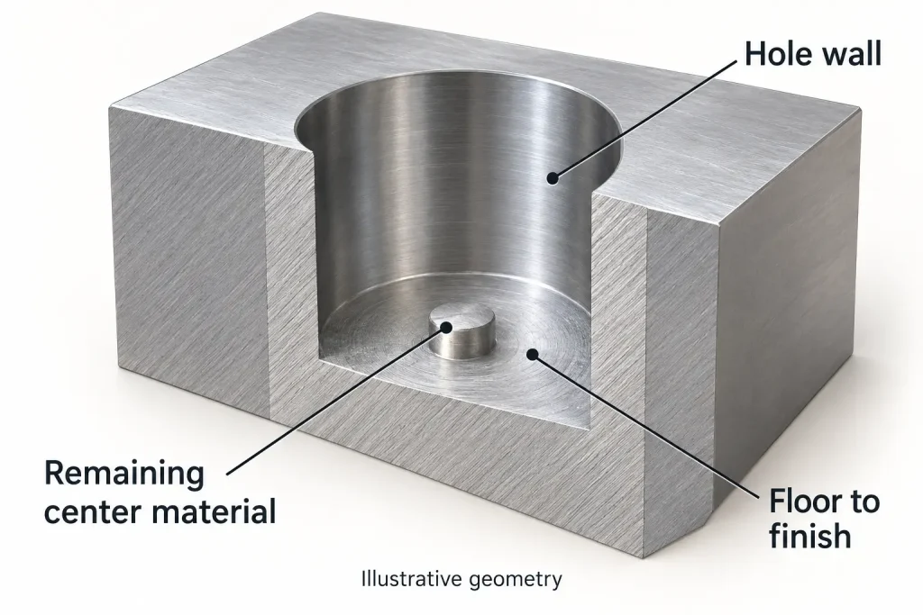
If the intended orbit cannot clear the center, the route may need a prepared opening or additional material-removal paths. That changes the operation being priced and programmed. A through-hole also needs a controlled plan for any remaining core as the cut breaks through.
For a blind hole, reaching the final Z coordinate does not prove that the floor is flat or that the full cylindrical wall is usable. Review remaining center material, the cutter’s corner geometry, and the path needed to finish the floor. Our blind hole design guide explains how to distinguish usable feature depth from total depth.
Chip removal needs space throughout the descent. A satisfactory entry cut does not establish that the same arrangement will evacuate chips at full depth. Review flute reach, holder clearance, coolant access, and how chips leave the hole before increasing pitch to shorten the cycle.
Decide What Finishes the Functional Bore
Helical milling may create the finished wall or prepare a hole for another operation. Make that choice from the drawing requirements and demonstrated process behavior.
For example, an interpolated clearance hole in a mounting plate and a bearing seat may have similar nominal diameters but very different requirements. The bearing seat can demand closer control of size, form, surface condition, and its relationship to other features. A common cutter does not make those requirements interchangeable.
A separate wall-finishing pass can control the stock removed after roughing. It still depends on tool condition, deflection, workholding, and machine motion. Correcting the programmed radius may change diameter, but it does not by itself correct taper, out-of-roundness, or an incorrect datum setup.
Where another finishing route is proposed, our reaming versus boring guide explains what the starting hole must provide. Reserve appropriate stock and access for that operation before machining the rough hole.
Compare routes at the same finished requirement. Fewer tools may simplify a small batch with varied diameters, while repeated standard holes may justify a different process. Include entry, chip clearing, wall and floor finishing, tool changes, and verification when comparing cycle time.
For a holemaking review through our CNC machining services, provide the material condition, hole sizes and depths, starting-stock geometry, bottom requirements, datum relationships, and quantity. Identify which holes provide clearance and which locate, support, or seal against another part. These details allow the proposed helical-milling and finishing sequence to be assessed before quotation.