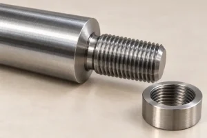

A threaded collar can turn freely along a shaft and still stop before its face reaches the shoulder. The obstruction may be the incomplete thread at the end, a corner radius, or a burr. Tightening harder does not establish that the intended faces are seated.
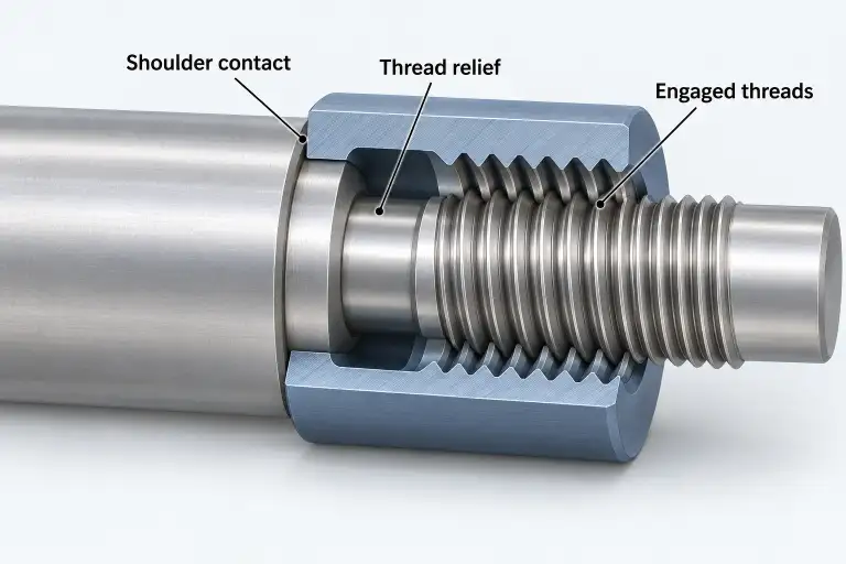
A thread relief is a deliberately recessed region at the end of a thread. It can provide space for the threading tool and clearance for the mating component. Its design must preserve enough complete thread engagement and enough material to carry the load.
For a shoulder-seated joint, check three things together: where the complete threads end, what must clear that transition, and which face must make contact. A groove that solves the tool-clearance problem can still leave an assembly problem.
A Thread Runout Is Not a Relief Groove
Thread runout is the transition where the thread becomes incomplete as it ends. A thread relief groove is intentional material removal that provides clearance near that end. The terms describe related features, but they should not be used as interchangeable drawing notes.
An entry chamfer serves another purpose. It guides assembly and removes the sharp edge at the thread entrance. A small chamfer on the mating collar does not automatically clear the shaft’s entire thread runout or shoulder radius.
Consider an externally threaded shaft with a larger-diameter shoulder. A collar must screw onto the shaft until its end face contacts that shoulder. If the collar’s internal thread reaches an obstructing transition first, the assembly can feel tight while a gap remains between the faces.
Possible design responses include a relief at the shaft’s thread end, a suitable clearance recess in the collar, or a change in the required thread and shoulder positions. These choices remove material from different places. Review the remaining engagement, the collar’s bearing area, and the shaft section before choosing one.
Define the intended contact face and the clearance around the thread end separately. A thread relief is not a sealing feature unless it has been specifically designed and validated for that function.
Put the Mating Collar at Its Final Position
Thread length on either component alone does not establish how much complete thread overlaps in the assembled joint. Move the mating parts to their final positions, then compare the regions that contain complete thread profiles.
The following is an illustrative axial-layout example, not a standard relief design or a thread-strength calculation. Assume compatible threads, sufficient radial clearance, and a collar that can reach the shoulder without interference. Ignore tolerances and elastic deformation for this first check.
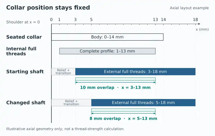
Set the shoulder face at x = 0 mm. Measure x outward along the shaft toward its free end. The seated collar extends from x = 0 to x = 14 mm.
| Feature in the seated assembly | Axial region | Meaning |
|---|---|---|
| Complete external thread on the shaft | x = 3 to 18 mm | The region nearer the shoulder is reserved for relief and transition geometry |
| Complete internal thread in the collar | x = 1 to 13 mm | Entrance and exit details are excluded from the complete-profile region |
| Region where both complete profiles overlap | x = 3 to 13 mm | The shared axial length is 10 mm |
| Overlap after the shaft’s complete thread starts at x = 5 mm | x = 5 to 13 mm | The shared axial length falls to 8 mm |
For the starting geometry:
Axial overlap = 13 − 3 = 10 mm
If a wider relief and transition move the start of the complete external thread to x = 5 mm:
Axial overlap = 13 − 5 = 8 mm
The collar can still reach the same shoulder in this assumed geometry. The change has reduced the overlap without changing the collar’s overall width or its final seating position.
A seated collar does not prove that the required length of complete threads remains engaged. Conversely, sufficient overlap does not prove that the intended faces make contact.
For production, repeat the layout check using the permitted axial limits, including relief position, thread-end limits, collar thickness, entrance details, and any intervening washer or spacer. Identify the combination that produces the smallest axial overlap of complete thread profiles, and compare that overlap with the required minimum engagement. Separately check the combination most likely to obstruct seating.
This geometric check does not establish thread-stripping strength or load capacity. Those depend on the thread geometry, both materials, loading, and the applicable design method. Do not assume that every engaged turn carries an equal share of the load.
Give the Tool Space Without Removing Unnecessary Material
Relief width, diameter, and transition radius answer different questions. Width provides axial room. Diameter establishes radial clearance. The radii affect the tool path, mating clearance, and local stress concentration. Specifying only one of these dimensions leaves the others unresolved.
For an external thread, a relief reduces the local shaft diameter. For an internal thread, a relief enlarges the bore locally. A note such as “0.5 mm relief” is therefore incomplete unless it identifies the dimension and its reference.
The tool needs clearance for its actual cutting geometry and motion, not merely for the point shown in a simplified drawing. Sandvik Coromant’s thread-turning insert guidance identifies a specific example: a multi-point insert needs room beyond the last thread for its final tooth to clear. A groove suited to one insert arrangement may not suit another.
The machine’s threading cycle and withdrawal path also need review. A groove can provide space for withdrawal, but its presence alone does not establish that the insert and holder will clear the shoulder. Check the proposed tool assembly and path before locking a very narrow relief into the drawing.
Where a standard relief is appropriate, identify the standard, required form, and edition. DIN 76-1:2025-10 covers runouts and undercuts for the ISO metric threads within its scope, including relevant internal-thread features. Use the applicable document to select dimensions and the designation. Do not extend a metric-thread table to Unified, pipe, or another thread system without an appropriate basis.
A general note such as “relief per DIN 76” may leave the applicable part or form unresolved. Likewise, a fixed multiple of pitch should not replace the required standard and tooling review. If a custom relief is needed, dimension its geometry and tolerances explicitly.
Increasing clearance can create a different risk. A deeper external groove reduces the shaft’s remaining cross-section. A larger internal recess reduces the surrounding wall. The groove’s transitions also require attention where bending, torsion, or repeated axial loading is important. A radius can reduce the severity of a sharp notch, but it must still clear the mating component and the tool.
The useful relief is the one that satisfies tool clearance, assembly clearance, and the remaining-section requirement together. Extra depth is not automatically extra safety.
For an internal thread near a blind bottom, distinguish a circumferential relief from extra axial hole depth. A local enlargement may provide radial space, but it does not remove the need for tool-end clearance or chip evacuation. Our blind hole design guide explains the separate usable-depth and bottom-clearance requirements.
When space is restricted, review whether a different threading route can meet the required complete-profile extent. Cutter access, reach, and entry and exit motion still need checking. The thread milling versus tapping guide covers that internal-thread process decision; a change of process does not remove the need to verify the assembled joint.
Make the Thread End an Inspectable Drawing Requirement
A thread size and tolerance class do not, by themselves, define the shoulder transition. Add a section or local detail that makes the complete-thread boundary, relief, and seating face clear.
For this feature, the drawing review should resolve:
- The thread standard, size, pitch, and tolerance class, together with the required extent of complete threads.
- The permitted runout or relief region, located from an identified face.
- The relief diameter, axial width, and transition radii, or an unambiguous standard designation.
- The shoulder’s required contact area and any mating chamfer or clearance recess.
- The acceptance condition after deburring and any specified finishing operation.
Use tolerances that reflect these functions. Avoid independently tightening several linked dimensions if their limits make the required geometry inconsistent. A supplier needs a clear permitted region for the transition, not conflicting requirements for complete threads and a groove in the same space.
Thread gauging and end-feature inspection should address their respective requirements. Use the specified thread gauges and procedure for thread acceptance. Separately establish the complete-thread extent, relief geometry, and shoulder condition where the drawing requires them. Gauge entry geometry or shoulder contact can limit access. Counting how many turns an ordinary mating nut makes before it stops does not, by itself, verify these requirements.
An accessible external relief may be checked by optical profile measurement or suitable dimensional equipment. An internal relief may need a dedicated gauge or another method suited to its access and tolerances. Agree on that method before production if ordinary tools cannot reach the controlled surfaces.
Inspect the boundary between the last thread and the groove for raised or loose burrs. Deburring must remove unwanted material without moving the complete-thread boundary beyond its permitted limit or damaging the seating face. If coating is specified, confirm the final thread and clearance requirements in the required delivery condition.
A mating-part check can help establish whether the intended faces seat, but one successful pair does not demonstrate interchangeability across all allowed dimensions. Keep the assembly check and dimensional acceptance connected to the same drawing requirements.
For a shoulder-threaded shaft or internally threaded collar, include the mating section and final assembly position with the drawing. Mark the required complete-thread engagement and any limits on groove depth or remaining wall. Through our CNC turning services, RapidEfficient can review the proposed relief, tooling access, and inspection approach before quotation.